

MOLDBOARD LOCKING HOOKS AND SHAFT REPLACEMENT (Sheet 6 of 6)
12.
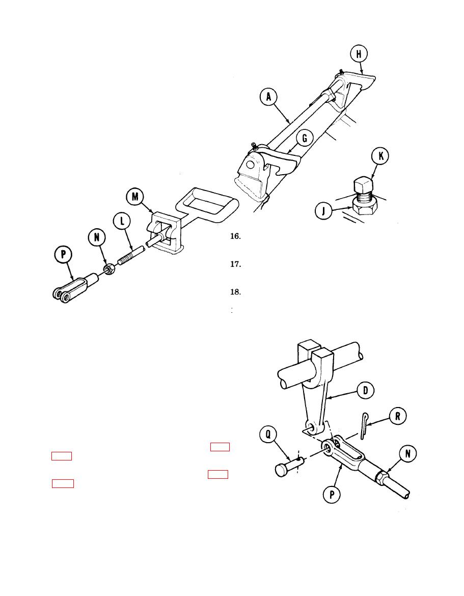
Install nut (J) onto bolt (K).
13.
Install bolt (K) and nut (J) into holes on hooks
(G) and (H) as shown.
14.
Using 1/2 inch wrench, tighten bolt (K) into
hooks (G) and (H). Using 3/4 inch wrench, back
off nut (J) as much as needed to make sure bolt
(K) is tight on shaft (A).
Using 3/4 inch wrench, tighten nut (J).
15.
Install handle (L) through bracket (M) in
`locked' position as shown (bottom slot).
Using 3/4 inch wrench, install nut (N) onto
handle (L).
Start clevis (P) onto handle (L) by hand.
19.
Using adjustable wrench, turn clevis (P) onto
handle (L) until the number of turns that
were recorded during removal is obtained.
20. Install clevis (P) onto arm (D) with pin (Q).
21. Install new cotter pin (R) into pin (Q) and using
pliers, bend ends of cotter pin over onto pin (Q).
22. Using 3/4 inch wrench on nut (N), tighten nut
(N) onto clevis (P).
23. Install guards on hydraulic ram cylinders (page
24. Install left front fender support assembly (page
End of Task
TA141127
18-25
