

TM 9-2360-222-20-1-4
BRAKE PRESSURE GAGE AND RELATED PARTS REPLACEMENT (Sheet 1 of 4)
PROCEDURE INDEX
PAGE
PROCEDURE
Removal
Installation
Ratchet with 1/2 in. drive
TOOLS:
Slip joint pliers
3/4 in. combination box and open end wrench
13/16 in. combination box and open end wrench
11/16 in. combination box and open end wrench
7/16 in. combination box and open end wrench
7/16 in. socket with 1/2 in. drive
5 in. extension with 1/2 in. drive
Container (to catch brake fluid)
SUPPLIES:
3/4 in. plastic cap
Silicone brake fluid (Item 34, Appendix D)
Lockwasher (MS35338-44 (2 required)
TM 9-2350-222-10
REFERENCE:
Place shift lever in N (neutral) position (TM 9-2350-222- 10)
PRELIMINARY
PROCEDURES:
Block tracks (TM 9-2350-222-10)
REMOVAL:
NOTE
Clean all parts and general
area prior to removal.
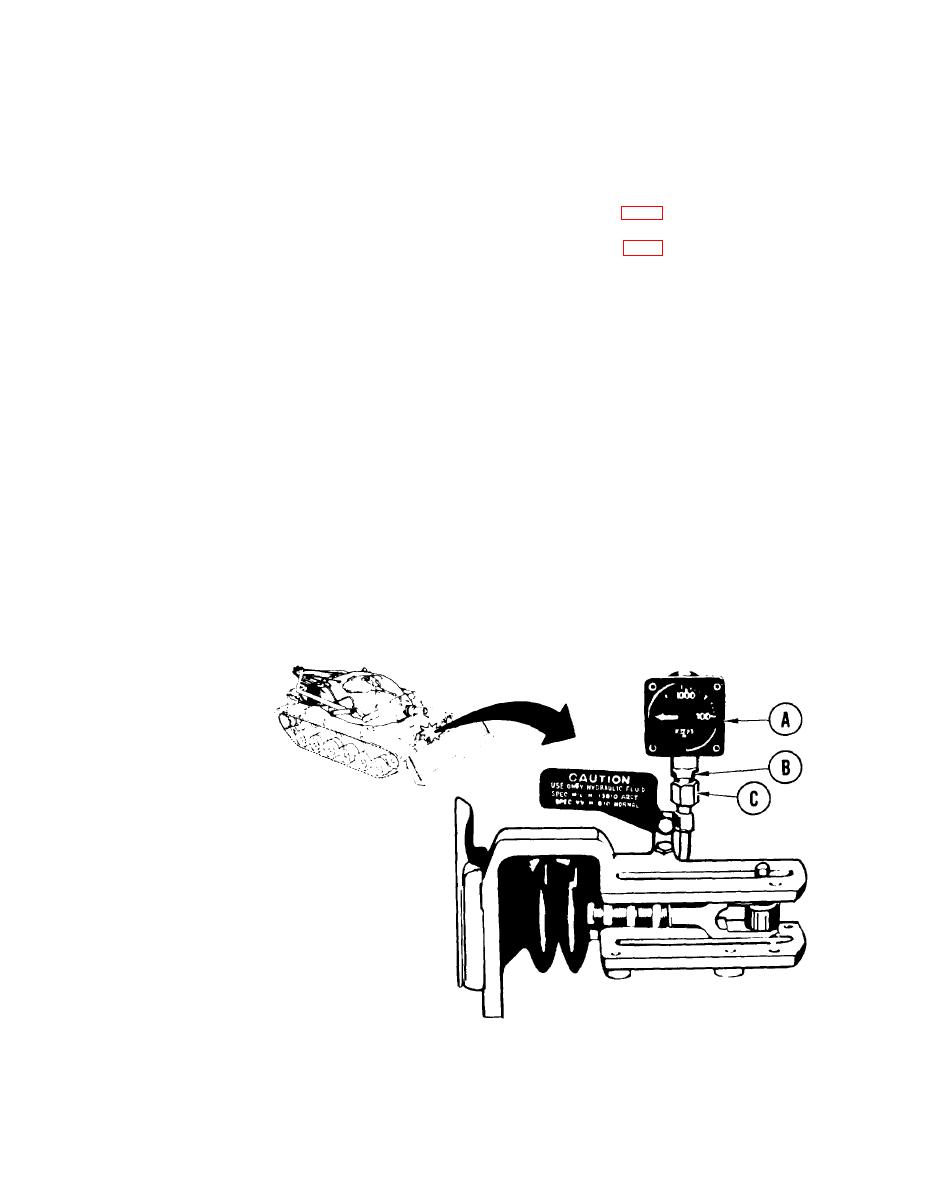
Position container under gage (A) to catch
1.
brake fluid.
2.
Using 13/16 inch wrench to hold reducer
(B) and, using 11/ 16 inch wrench, loosen
tube assembly nut (C). Allow brake fluid
to drain into container.
Go on to Sheet 2
TA253428
13-36 Change 1
