

TM 9-2350-222-20-1-3
ENGINE COOLING FAN SHROUD REPLACEMENT (Sheet 8 of 8)
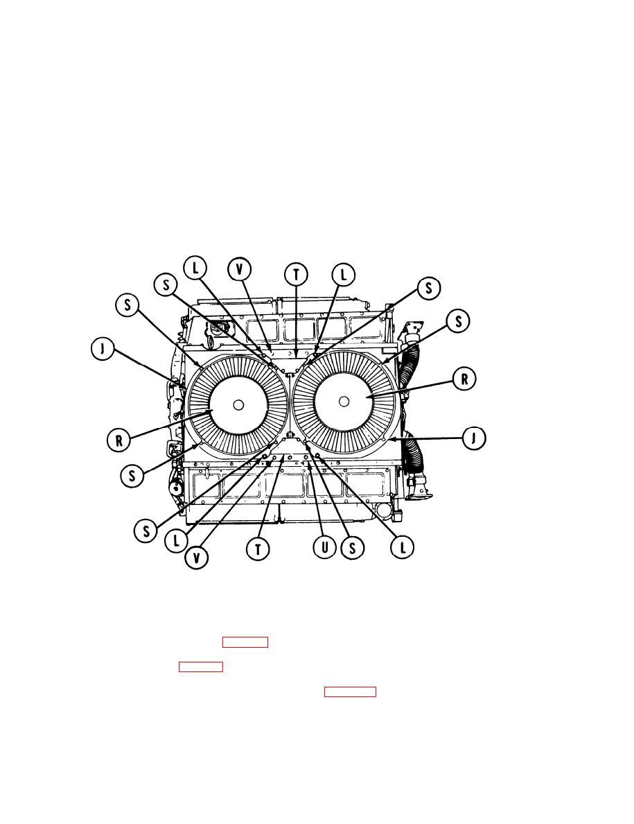
Using thickness gage, check clearance between tip of each fan blade and fan housing (J). If
17.
clearance is less than 0.062 inch (0.157 mm) all around, loosen screws.(L) and shift fan housing (J)
as necessary to obtain clearance.
When clearance is obtained, use 9/16 inch socket and tighten screws (L).
18.
Position two fan guards (R) onto fan housing (J).
19.
Install eight bolts and new lockwashers (S) to secure fan guards (R) to fan housing (J).
20.
Using 9/16 inch socket, tighten bolts (S).
21.
22.
Position two cover plates (T) onto shroud (U).
23.
Using 1/2 inch socket, install five bolts (V) to secure each cover plate (T).
Install engine shroud supports (page 9-5).
24.
Install engine shroud (page 9-3).
25.
26. Install 2A powerplant (page 5-14) or 2D powerplant (page 5-37).
TA140292
End of Task
9-58
