

TM 9-2350-222-20-1-3
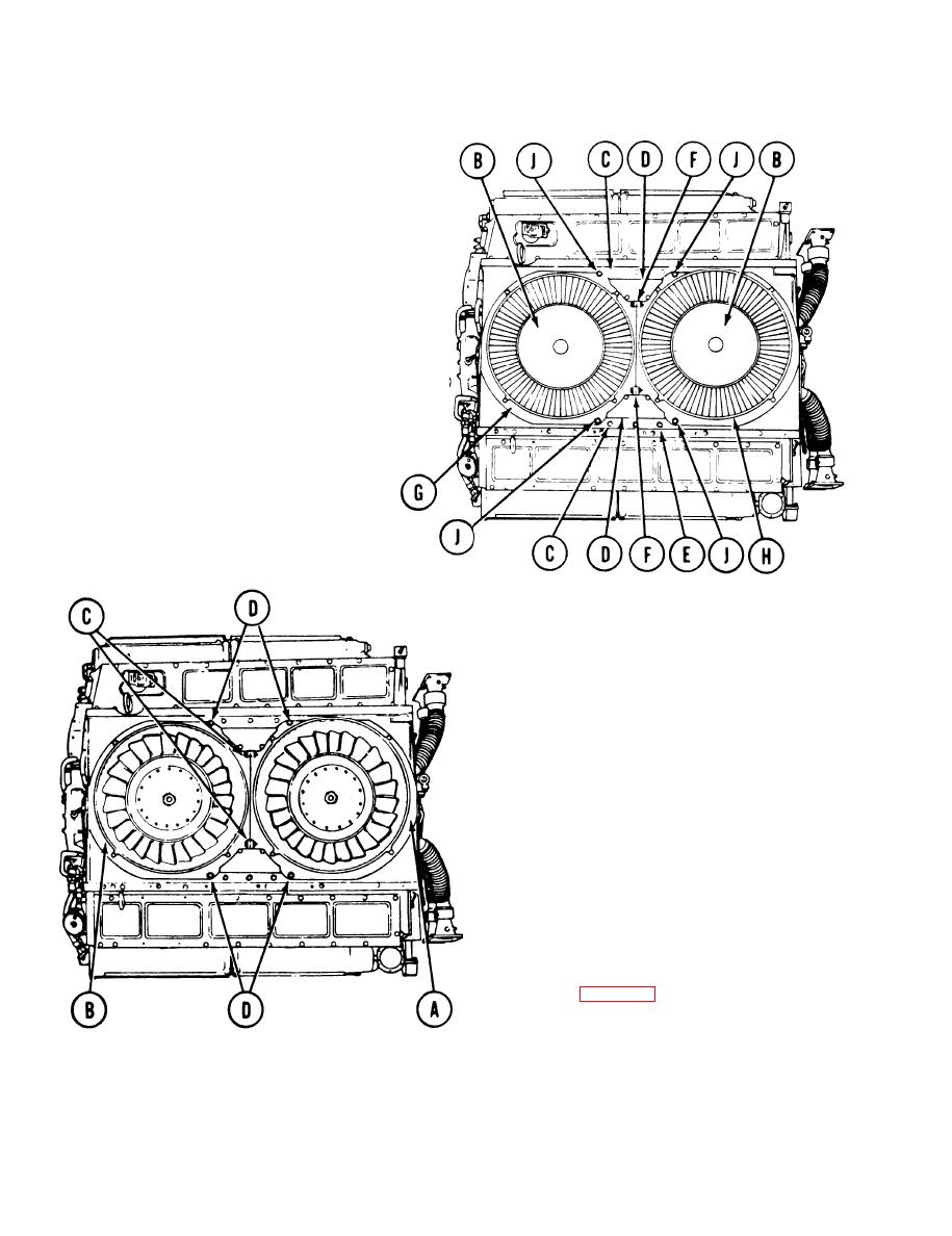
CENTRIFUGAL FAN HOUSING REPLACEMENT (Sheet 2 of 3)
Remove fan housings (B) from powerplant.
2.
Using 1/2 inch socket, remove ten screws (C)
3.
securing covers (D) to shroud (E).
4.
Remove covers (D) from powerplant.
Using two 9/16 inch wrenches, remove two
5.
screws, washers, and self-locking nuts (F) that
hold housing (G) and mount (H) together.
Throw self-locking nuts away.
Using 9/16 inch socket, remove four screws (J)
6.
Remove housing (G) and mount (H) from
7.
powerplant.
INSTALLATION:
NOTE
Make sure no foreign matter is
present in fan housing.
1.
Position mount (A) and housing (B) onto
powerplant.
2.
Using two 9/16 inch wrenches, install two
screws, washers, and new self-locking nuts (C)
securing mount (A) and housing (B) together.
3.
Using 9/16 inch socket, install four screws
(D) securing mount (A) and housing (B) to
engine shroud.
Using feeler gage, check clearance between
tip of each fan blade and mount (A) and
housing (B). If clearance is less than 0.062
inch, go to page 9-58, steps 17 and 18 for
adjustment procedures.
TA140294
Go on to Sheet 3
9-60
