

TM9-2350-222-20-1-3
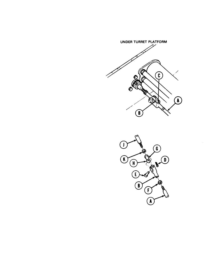
ACCELERATOR LINKAGE ADJUSTMENT (Sheet 2 of 8)
ADJUSTMENT
1.
Open turret platform access door and traverse
turret to position gun tube over right front
fender stowage box (TM 9-2360-222-10).
2.
Check to see if threaded shaft (A) is flush with
inside of clevis (B) at location (C). If threaded
shaft is flush, go to step 6. If threaded shaft is
not flush, go to steps 3, 4, and 5.
3.
Using pliers, remove cotter pin (D) and pin (E).
Throw cotter pin away.
4.
Using 9/16 inch wrench to hold clevis (B), use
1/2 inch wrench to loosen nut (F) and adjust
clevis (B) so that shaft is flush with clevis.
5.
Using 9/16 inch wrench to hold clevis (B), use
1/2 inch wrench to tighten nut (F).
6.
Insert 1/16 inch diameter pin at location (G) in
rod end bearing (H) to be sure that threads of
tube assembly (J) go into rod end bearing
beyond location (G). If tube assembly is not
inserted beyond location (G), go to steps 7 and
8. If tube assembly is inserted beyond location
(G), go to step 9,
7.
Using 7/16 inch wrench to hold (on flats) rod
end bearing (H) and 1/2 inch wrench to loosen
nut (K), adjust rod end bearing as stated in step
6.
8.
Using 7/16 inch wrench to hold (on flats) rod
end bearing (H), use 1/2 inch wrench to tighten
nut (K).
NOTE
Rod (H) or clevis (B) may be pulied
in order to insert pin (E).
9.
Insert pin (E) and, using pliers, install new cotter pin (D).
Go on to Sheet 3
TA149112
7-416
