

TM 9-2350-222-20-1-3
POWERPLANT REPLACEMENT (2D ENGINE) (Sheet 6.2 of 23)
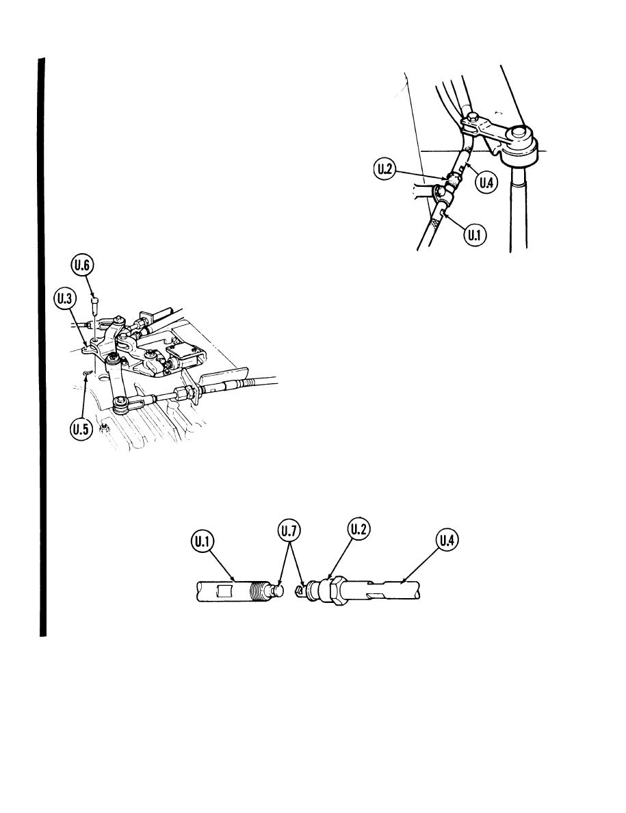
16.4. Using an adjustable wrench on the flats of
control assembly (U.1) and 7/8 inch
wrench on disconnect nut (U.2), loosen nut.
16,5 With shift lever in park `P' position, manu-
ally move bellcrank (U.3) at top of transmis-
sion fully clockwise,
NOTE
This will force the two control
assemblies (U.1 and U.4) to open
up at the disconnect point.
16.6. Using pliers, remove cotter pin (U.5) and
remove straight pin (U.6).
16.7 Manually disconnect the inner pushrods (U.7) of the control assemblies (U. 1 and U.4 and move control
assembly (U.4).
TA253171
Go on to Sheet 7, step 21.
5-30.2 Change 1
