

TM 9-2350-222-34-1
FINAL DRIVE REPAIR (Sheet 30 of 30)
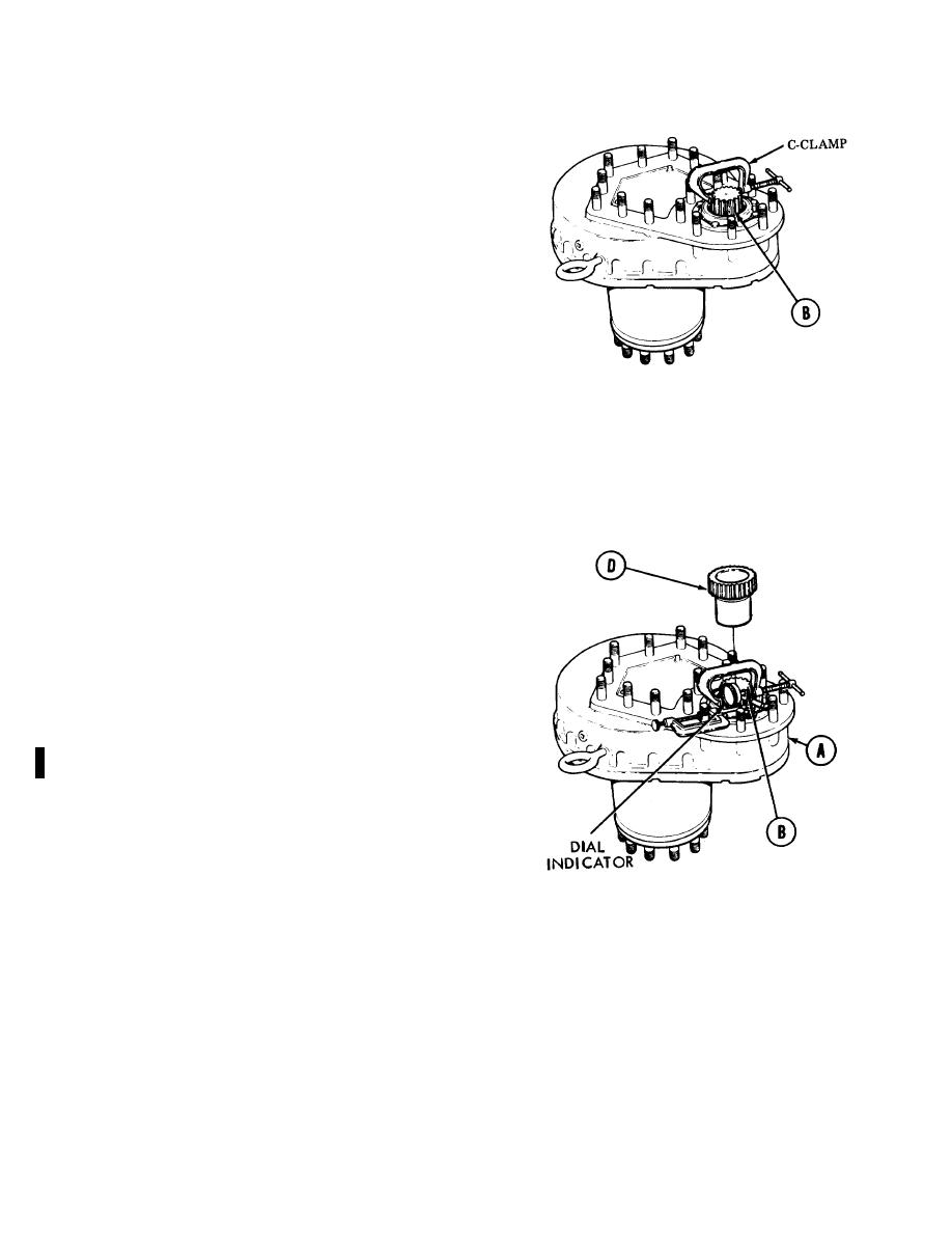
5.
Using C-clamp, rotate pinion gear shaft (B)
counterclockwise until slight pressure (drag) is
felt.
NOTE
Ensure pinion splines are clean and
free of chips, burrs, oil, and dirt
before installing dial indicator.
6.
Install dial indicator. Set dial indicator to zero.
7.
Rotate pinion shaft (B) clockwise until slight
pressure (drag) is felt.
8.
Record dial indicator reading.
9.
Remove dial indicator. Rotate pinion shaft (B)
one complete revolution.
10.
Repeat steps 5 thru 9 three times.
11.
If all four readings are between 0.006 and 0.032
inches (0.15424 and 0.8128 mm), remove
Clamp and install adapter (D). Package final
drive (A) for shipment and return to supply. If
readings are not within tolerance, go to step 12.
12.
Replace pinion gear and drive gear (matched set.) (Disassemble steps 1 thru 29.) (Assembly steps 54 thru 86.) If
replacement gears are not within tolerance, tag final drive (A) "UNSERVICEABLE (BACKLASH)" and return to
supply for depot rebuild.
End of Task
Change 5 7-30
