TM 9-2350-222-20-1-5
DRIVER'S SEAT ADJUSTING ASSEMBLY REPAIR (Sheet 5 of 10)
22.
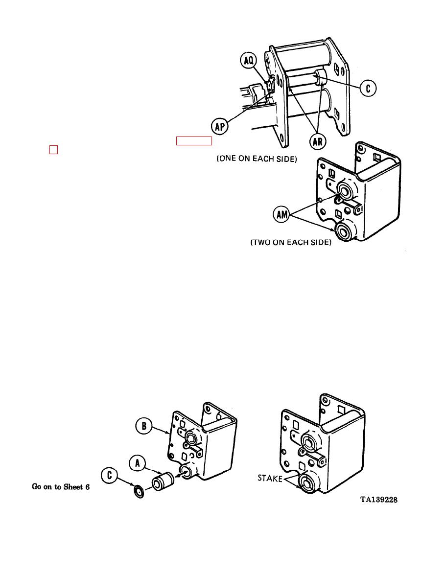
Using pliers, remove two clips (AP) from pin
(AQ).
Using hammer and 3/8 inch punch, remove pin
23.
(AQ) and bearings (AR) from housing (C).
CLEANING AND INSPECTION:
1.
Using dry cleaning solvent (Item 54, Appendix
Inspect all parts for damage or wear.
2.
Inspect four shaft bearings (AM) in adjusting
3.
assembly. Replace if required.
4.
Replace all damaged or worn parts.
NOTE
If bearings (A) are to be replaced, perform steps 1 thru 5 for
each bearing and seal. If bearing replacement is not required,
proceed to step 6.
ASSEMBLY:
1.
Using file, remove retaining stake marks from bracket (B).
2.
Using hammer and 3/8 inch punch, drive bearing (A) and seal (C) from bracket (B).
Using vise, press new bearing (A) into bracket (B), and recess with 3/4 inch brass drift to allow fit
3.
of seal (C).
4.
Using 3/4 inch brass punch, install seal (C).
5.
Using hammer and chisel, stake each seal (C) at three equally spaced points.


