TM 9-2350-222-20-1-5
DRIVER'S SEAT ADJUSTING ASSEMBLY REPAIR (Sheet 9 of 10)
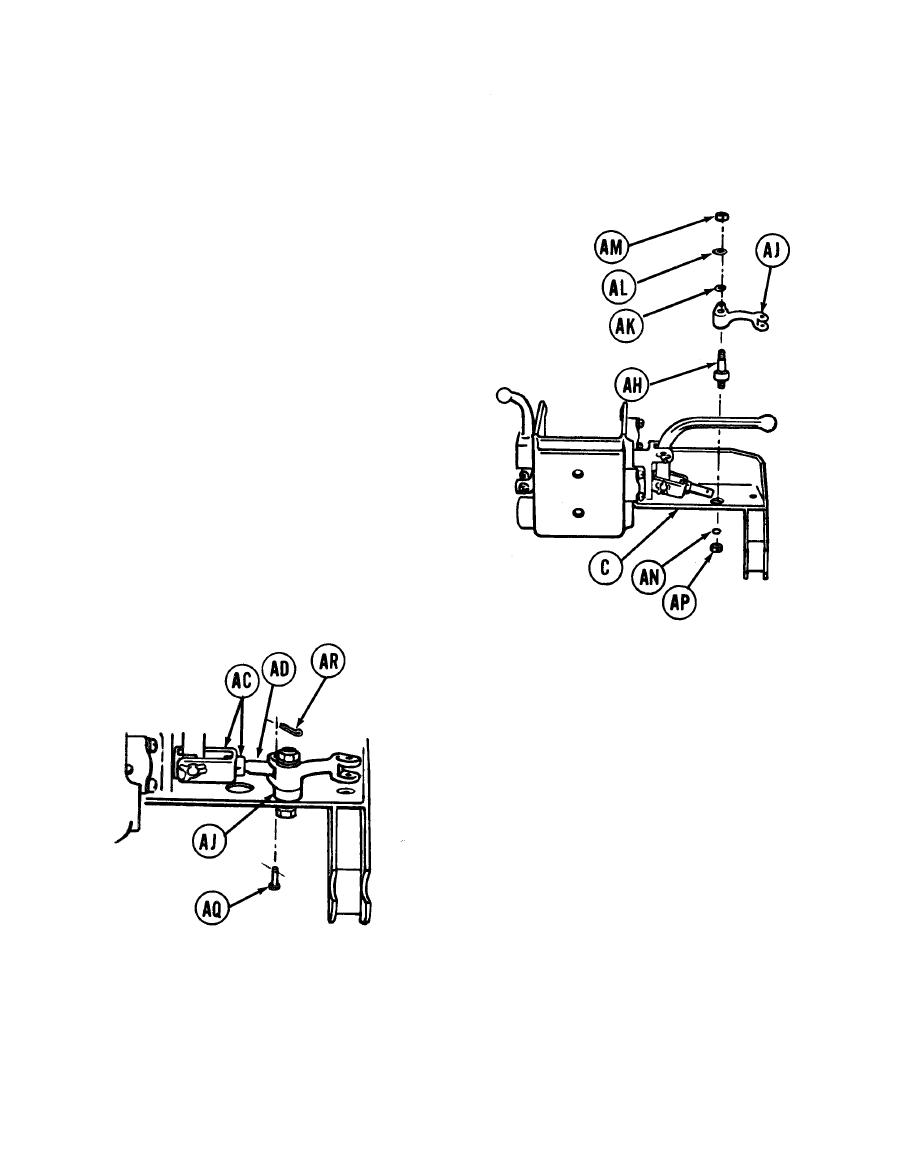
26. Position stud (AH) in bracket (C) with holes
alined.
27. Position bellcrank (AJ) on stud (AH).
28. Position flat washer (AK), new lockwasher (AL),
and nut (AM on top of stud (AH).
29. Tighten nut (AM) finger tight.
30. Position new lockwasher (AN) and nut (AP) in
bottom of stud (AH).
31. Install nut (AP) finger tight.
32. Using fingers, adjust length of link (AD) by
turning nuts (AC) until hole in link (AD)
alines with hole in bellcrank (AJ).
33. Using hammer and punch, install pin (AQ)
through hole in bellcrank (AJ) and link (AD).
34. Using pliers, install new cotter pin (AR) in
pin (AQ).
35. Using one 9/16 inch wrench, tighten two
nuts (AC).
Go on to Sheet 10
TA139232
17-31


