TM 9-2350-222-20-1-4
SHIFT LINKAGE ADJUSTMENT (Sheet 3 of 20)
6.
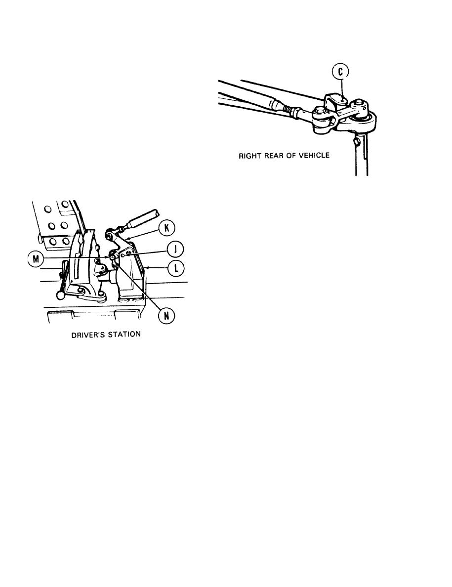
Go to right rear of vehicle and try to insert
locating pin into alinement hole (C). If locating
pin cannot be inserted, go to step 7. If locating
pin can be inserted, go to step 130.
7.
At driver's station, try to insert locating pin
into alinement holes (J) in link (K) and
bracket (L). If locating pin can be inserted,
remove locating pin and go to step 13. If
locating pin cannot be inserted, go on to step
8.
Using 9/16 inch wrench, remove screw (M).
8.
Manually move link (K) and insert locating
9.
pin in alinement hole (J).
10.
Using 9/16 inch wrench, adjust shifting rod bearing end (N) by turning clockwise or
counterclockwise until screw (M) slips freely through link (K) and shifting rod bearing end (N).
Remove locating pin from alinement hole (J).
11.
12.
Using 9/16 inch wrench, install screw (M). Using 9/16 inch socket and torque wrench, tighten
screw (M) to 15-20 1b-ft (2027 N.m).
Go on to Sheet 4
TA139257
,
11-4


