TM 9-2350-222-20-1-4
SHIFT LINKAGE ADJUSTMENT (Sheet 4 of 20)
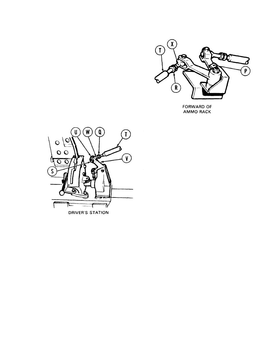
13. Forward of ammunition rack, try to insert
locating pin into alinement hole (P). If locating
pin can be inserted, remove locating pin and go
to step 43. If locating pin cannot be inserted,
go on to step 14.
14.
Using 9/16 inch wrench, loosenn jamnuts (Q)
and (R).
Using 9/16 inch wrench, remove screw (S).
15.
16.
Manually move shifting rod (T) and insert
locating pin into alinement hole (P).
17.
Using 9/16 inch wrench, adjust shifting rod
bearing end (U) by turning clockwise or
counterclockwise until screw (S) slips freely
through link (V) and shifting rod bearing end
(U).
18. Using small diameter wire (Item 59, Appendix D), check to see if shifting rod (T) is past holes (W)
and (X). If shifting rod (T) is past holes (W) and (X), do steps 19 thru 22. If shifting rod (T) is not
past hole (W), do steps 23 thru 32. If shifting rod (T) is not past hole (X), go to step 33.
Go on to Sheet 5
TA 139258
11-5


