Preparation for Special Shipping Width
The machine should be prepared for special shipping
width when it is necessary to reduce the width of the
machine to 2591 mm (102 in).
NOTE: The following procedure is for reducing the
shipping width of the machine by collapsing the blade.
There may be other steps required to fully prepare the
machine for shipping. Refer to “Operation Section,
Transportation Information” in the Operator’s Manual.
1. Drive the machine onto the transport vehicle, park
the machine in position for shipping, and apply the
parking brake.
NOTE: It is possible to perform this procedure while
the machine is not on the transport trailer, and then
drive the machine onto the transport trailer after the
blade has been collapsed. However, care must be
taken not to operate the blade angle function while the
blade is collapsed, to avoid damaging the angle
cylinders.
2. Angle the blade fully in the desired direction, and
put the blade in position 25 mm (1.0 in) off the deck
of the transport vehicle.
NOTE: The blade must be off the deck of the
transport machine to allow manual positioning of the
blade after the angle cylinders are disconnected.
3. Stop the engine. Refer to “Operation Section,
Machine Parking, Engine Stopping,” in the
Operator’s Manual.
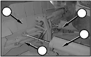
4. Remove bolt (2), pin retainer (3), and pin (1) from
retracted angle cylinder (4) and extended angle
cylinder (5). Put the pins, bolts and retainers in a
location where they will not be lost during transport.
NOTE: It may be necessary to drive pin (1) in the right
angle cylinder down in order to remove the pin.
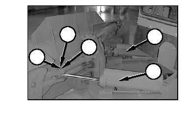
5. Slide angle cylinders (4) and (5) with the spacers out
of single tree (7). Collect the spacers, and place
them in a location where they will not get lost
during transport.
6. Rotate blade (6) by hand until the blade stops
against the singletree.
7. Slowly move the blade control lever into the down
position to allow the blade to rest on the transport
vehicle deck.
NOTE: It is not necessary to start the machine to
lower the blade. The blade will lower under its own
weight when the blade control valve is moved into
LOWER. If the start switch is in the ON position, the
machine must be in EARTHMOVING mode to lower
the blade.
8. Secure the blade in the fully angled position to
ensure that it does not move during transport.
9. Secure angle cylinders (4) and (5) to keep the rod
eyes from moving during transport. Make sure that
the chrome portion of the cylinders will not come
into contact with any hard surfaces during
transport.
NOTICE
Do not wrap metal chains or other metallic retainers
around the chrome portion of the angle cylinders.
Damage to the chrome surfaces will cause the
cylinders to leak and allow dirt into the hydraulic
system.
10. Cover the exposed chrome portion of the cylinders
in a suitable material to protect the chrome from
damage during shipment.
6
4
7
5
1
2
3
4
5
E-7
Appendix E
Unit Level Transportation Information
TM5-2430-200-10