15. Verify that suspension manual lockout valve (23,
on both sides of the machine) are turned fully
clockwise to the OPEN position.
NOTE: The following procedure is for reconfiguring
the machine after it has been air dropped.
NOTE: Before the cab is replaced, the integrity of the
seals between the cab and the platform should be
checked. Replace the seals if necessary. Reseal any
areas that may leak with 4C9613 RTV Silicone-
Clear.
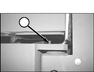
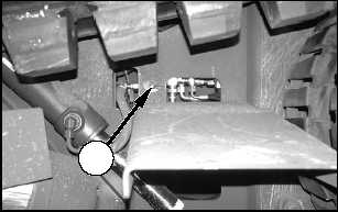
16. Lower the cab on guide pins (20) at the rear of the
cab platform.
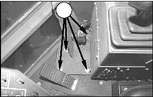
NOTE: Pay close attention when lowering the cab
onto the platform. Make sure that the cab does not
damage accelerator pedal (22), instrument console
(21), or the back of the operator’s seat.
17. Install four bolts (17) with the washers in the left
rear corner of the cab. Tighten the bolts to a
torque of 460 ± 60 N•m (340 ± 45 lb ft).
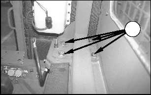
18. Install four bolts (16) with the washers in the right
rear corner of the cab. Tighten the bolts to a
torque of 460 ± 60 N•m (340 ± 45 lb ft).
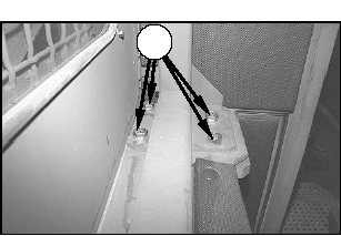
19. Install four bolts (15) with the washers in the right
front corner of the cab. Tighten the bolts to a
torque of 460 ± 60 N•m (340 ± 45 lb ft).
15
16
17
20
23
E-4
Appendix E
Unit Level Transportation Information
TM5-2430-200-10