NOTE: The following steps are for returning the blade
to normal service after the blade has been prepared
for special shipping width.
11. Remove all of the tie-down fasteners and
protective coverings from the blade and the angle
cylinders.
12. Start the engine. Refer to “Operation Section,
Engine Starting” in the Operator’s Manual.
13. Raise the blade until it is approximately 25 mm (1
in) above the transport vehicle deck.
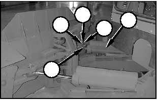
14. Move rod eye (8), of extended angle cylinder (5)
into position in singletree (7). Rotate the blade by
hand to achieve correct alignment between the
holes in the singletree and the hole in the rod eye.
15. Install one spacer above and below the rod eye to
remove the vertical gap between the rod eye and
the singletree.
16. Install pin (1), retainer (3), and bolt (2).
17. Lower the blade to the ground, and apply slight
downward pressure to the blade to keep it from
rotating.
NOTE: The machine must be in EARTHMOVING
mode to lower the blade when the start switch is in
the ON position.
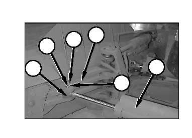
18. Put rod eye (9) of retracted angle cylinder (4) into
position in singletree (7).
19. Operate the blade angle function to extend or
retract the rod eye of retracted angle cylinder (4)
until the rod eye is aligned with the hole for the pin
in singletree (7).
20. Install one spacer above and below the rod eye to
remove the vertical gap between the rod eye and
the singletree.
21. Install pin (1), retainer (3) and bolt (2).
22. The blade is now ready for normal operation.
NOTE: Be sure grease the angle cylinder pins before
using the machine to do work.
1
2
3
4
9
1
2
3
7
8
5
E-8
Appendix E
Unit Level Transportation Information
TM5-2430-200-10