TM5-2430-200-10
F-1
Appendix F
PLGR Instructions
NOTE: For additional information about the PLGR,
refer to TM 11-5825-291-13, Operations and
Maintenance Manual, Satellite Signals Navigation Sets
AN/PSN-1 and AN/PSN-11(V)1.
NOTE: This appendix is not authorization for the
operator to maintain additional tools or perform
maintenance tasks.
1. Move the main disconnect switch to the OFF position.
Refer to “Operation Section, Maintenance Features,
Main Disconnect Switch.”
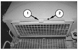
2. Remove plug (2) from the hole in the cab near
antenna mounting bracket (1).
3. Install the nonmetallic grommet in hole (2).
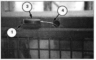
4. Use one 10-32 screw with a washer to install
antenna (3) on antenna mounting bracket (1).
NOTE: The screw is installed through the bottom of
mounting bracket (1).
5. From inside the cab, feed antenna wire (4) through
the hole, and connect the end of the wire to antenna
(3).
NOTE: Inside the cab, feed the end of antenna wire
(4), which attaches to the navigation set, through the
straps along the upper right side and down the right
side of the cab. Use wire ties to secure the wire to the
straps.
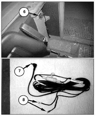
6. Use four 10-24 (16 mm [0.625 in] long) screws with
two washers and one 10-24 nut per screw to install
PLGR mount (5) to the mounting bracket on the
right console.
7. Connect end (8) of the power cord to power strip (6),
and end (7) to the navigation set.
NOTE: Power strip (6) is 24 volts. Route the power
cable through the same straps as the antenna cable.
Secure any excess power cable and antenna wire with
wire ties.