

MWO 9-2350-372-23-1
10. MODIFICATION PROCEDURES - Continued
g. Installation - Continued
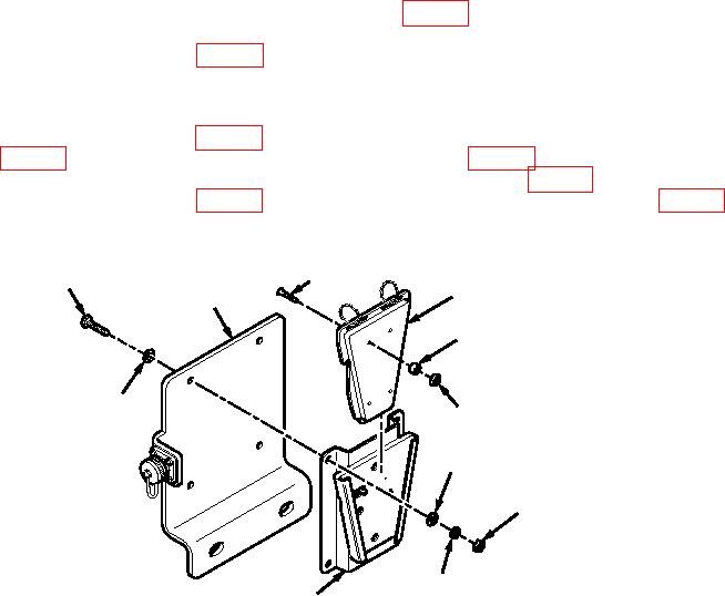
(2) Separate two pieces of JCAD interface kit 5-15-32039 (Figure 4, Kit 57K7628), as shown. Ensure that
four neoprene washers are installed on four screws on interface kit, and install four nuts
AEN15M508000CG2A41 (Figure 4, Kit 57K7628) on four screws when communications adapter is not
available.
(3) Apply sealing compound ASTM D5363 to threads of four hexagon head capscrews
AES01C250750AW9A91 (Figure 4, Kit 57K7628), and install JCAD interface kit 5-15-32039
(Figure 4, Kit 57K7628) on JCAD mounting bracket 12529156 (Figure 4, Kit 57K7628) with four
hexagon head capscrews, eight flat washers AEW24X25N000GF3CQ1 (Figure 4, Kit 57K7628), four
lockwashers MS35338-44 (Figure 4, Kit 57K7628), and four nuts J2295J995C2R04-PG5 (Figure 4,
Kit 57K7628), as shown. Reinstall two pieces of JCAD interface kit.
SCREW
AES01C250750AW9A91
5-15-32039
12529156
NEOPRENE WASHER
AEW24X25N000GF3CQ1
AEN15M508000CG2A41
AEW24X25N000GF3CQ1
J2295J995C2R04-PG5
MS35338-44
5-15-32039
JCAD003
Figure 4. JCAD Interface Kit Installation.
10