TM 9-2350-222-20- 1-4
SHIFTING CONTROL BRACKET AND CONNECTING LINK ASSEMBLY REPAIR AND
REPLACEMENT (Sheet 5 of 9)
5.
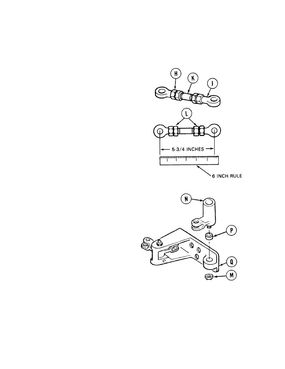
Using two 9/16 inch wrenches, remove rod
ends (H) and (J) from stud (K) if necessary.
6.
Using two 9/16 inch wrenches, install new
rod ends (H) and (J) on stud (K) as required.
7.
Using 6 inch rule, adjust length of rod assem-
bly to 5-3/4 inches center-to-center of rod end
holes.
Using 9/16 inch wrench to hold rod ends (H)
8.
and (J), and crowfoot wrench, adapter, and
torque wrench on jamnuts (L), tighten
jamnuts (L) to 15-20 lb-ft (20-27 N.m) while
maintaining 5-3/4 inch measurement.
Using 3/4 inch wrench, remove self-locking
9.
nut (M). Throw nut away.
Remove link assembly (N).
10.
Inspect bearing (P) and link (N). Replace if
11.
required.
NOTE
If bearing (P) is to be replaced,
perform steps 12 and 13. If not,
proceed to step 14.
Using 3/4 inch punch and hammer, remove
12.
bearing (P) from bracket (Q). Throw bearing
away.
Using vise, press new bearing (P) in bracket
13.
(Q).
Go on to Sheet 6
Change 5
11-56


