TM 9-2350-222-20-1-4
SHIFTlNG CONTROL BRACKET AND CONNECTING LINK ASSEMBLY REPAIR AND
REPLACEMENT
(Sheet 7 of 9)
ASSEMBLY:
NOTE
Position bracket (C) into vise as
necessary to accomplish assembly.
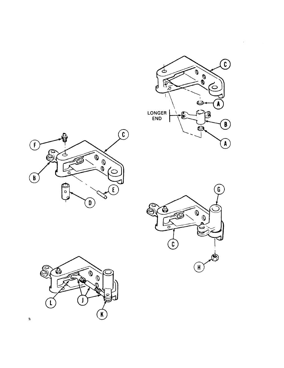
Position two washers (A) on connecting link (B).
1.
Carefully position washers (A) and connecting
2.
link (B) in bracket (C) with all holes alined.
Make sure longer end of connecting link is
inserted through bracket.
Position shaft (D) through bracket (C),
3.
washers (A), and connecting link (B) with pin
hole in shaft (D) alined with pin hole in
bracket (c).
Using hammer, install new pin (E) through pin
4.
hole in bracket (C) and shaft (D).
5.
Using 5/16 inch wrench, install grease fitting
(F).
Position link assembly (G) on bracket (C).
6.
7.
Using 3/4 inch wrench, install new
self-locking nut (H) on link assembly (G).
8.
Position stud and rod end bearing assembly
(J) with rod end holes alined with holes in
clevises (K) and (L).
Go on to Sheet 8
TA139311
11-58


