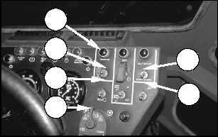
3. Place blackout light switch (6) in the STOP LIGHT
or SERVICE DRIVE position. Refer to “Monitoring
Systems and Cab Features, Switches” in this
section for details about positions of blackout light
switch (6).
4. Place the self-deploy/earthmoving switch into
SELF-DEPLOY position (7).
5. Move the kneeling switch down to LOWER (4), and
hold the switch in the LOWER position until
kneeling indicator (3) illuminates.
With the kneeling switch in the LOWER position,
the front of the machine lowers, reducing
clearance between the walkways and the drive
belts and also causing the blade position to
lower. Keep personnel clear of the machine when
lowering the machine.
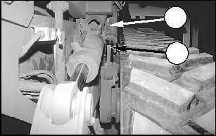
6. Use the pump handle to install the kneeling lock pin
on both sides of the machine when locking bar (10)
aligns with the hole in bracket (9).
NOTE: The kneeling lock pins and pump handle are
stored in the electrical panel and BII compartment at
the left rear of the machine.
NOTICE
The kneeling lock pins must be installed to secure the
machine in the kneeled position.
Do not operate the machine at speeds greater than 3
kph (2 mph) in the kneeled position.
7. Lower all grab rails. Refer to “Machine Features,
Grab Rails” in this section.
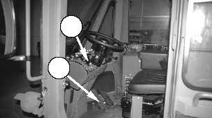
8. Move transmission control lever (11) to first gear,
and slowly drive the machine onto the aircraft.
9. When the machine is in place on the aircraft,
depress service brake pedal (12), and move
transmission control lever (11) into NEUTRAL.
With the engine running, this machine will spot
turn when the steering wheel is turned, even if
the transmission is in NEUTRAL.
To avoid personal injury due to unexpected
movement, engage the parking brake and make
sure the area is free of personnel before starting
the engine.
10. Pull knob (2) up to engage the parking brake
before releasing service brake pedal (12).
11. Place the self-deploy/earthmoving switch into
EARTHMOVING position (8).
WARNING
!
12
11
9
10
WARNING
!
7
8
3
4
5
6
83
Operation Section
Transportation Information
TM5-2430-200-10