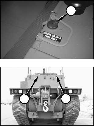
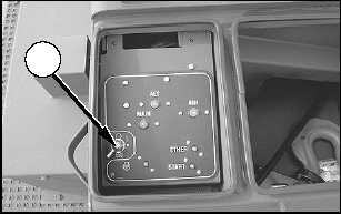
3. Open the electrical panel and BII compartment at
the rear of the machine, and turn main disconnect
switch (3) to the OFF position. Refer to “Machine
Features, Main Disconnect Switch” in this section.
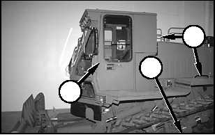
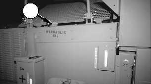
4. If necessary, install padlocks on start switch locking
pin (1), fuel tank cap (4), electrical panel and BII
compartment (5), tool/battery box (6), hydraulic tank
cap (7), and cab door (8).
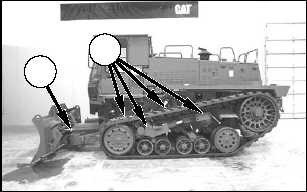
5. Dismount the machine, maintaining three-point
contact with hand holds (10) and step (9).
6. Inspect back side (11) of the blade and inside (12)
of the drive belt components on both sides of the
machine for any accumulation of debris. Clean out
any debris before the debris hardens.
11
12
8
9
10
7
5
6
4
3
78
Operation Section
Machine Parking
TM5-2430-200-10