

TM 9-2350-222-20-1-4
PARKING BRAKE CONTROL ASSEMBLY AND LINKAGE REPLACEMENT
(DRIVER'S STATION) (Sheet 7 of 10)
2.
Lay out removed and replacement control assemblies side by side. Make sure length of end
fittings match. Mark replacement control assembly at same location as mark on removed control
assembly.
3.
Go to engine compartment, Using safety wire
(Item 61, Appendix D) extending from behind
fuel tank, wrap threads of forward (short) end
of control assembly several times. Make sure
safety wire is tight around control assembly.
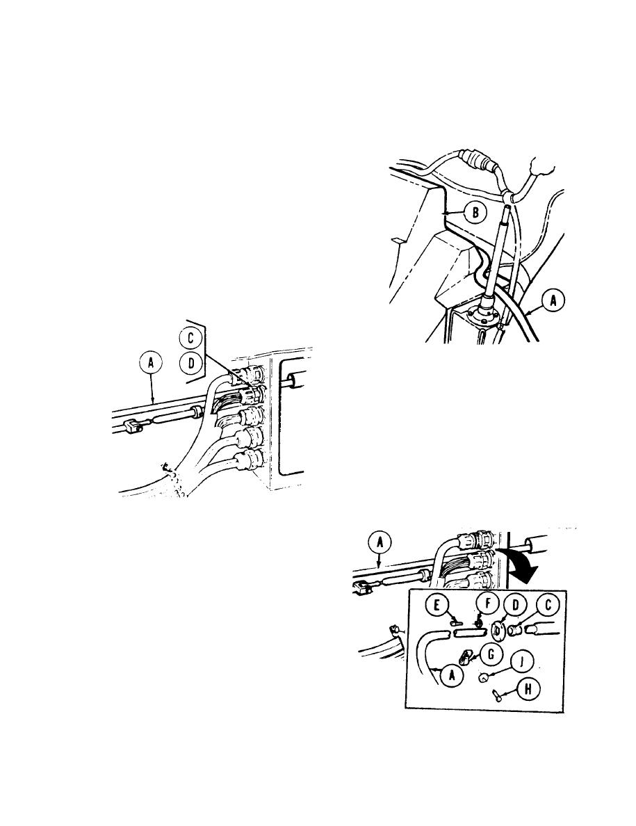
4.
With one person inside turret pulling safety
wire extending from bulkhead, second person
carefully threads control assembly (A) through
tube located behind fuel tank (B) until control
assembly end is visible at bulkhead inside
turret.
5.
Carefully pull control assembly (A) through
tube until reference mark on control
assembly is at bushing (C) and retainer (D)
location.
6.
Apply sealing compound (Item 23, Appendix
D) to new split bushing (C). Position bushing
(C) over control assembly (A). Allow 20
minutes for compound to dry, then install
bushing (C) into bulkhead.
7.
Position retainer (D) in place. Using
screwdriver, secure retainer (D) to bulkhead
with four screws (E) and four washers (F).
8.
Route control assembly (A) along right side of
hull behind periscope box and ammunition rack
and down into driver's station to base of
transmission shift control.
9.
Position clamp (G) over control assembly (A).
Using 1/2 inch socket, secure control to hull
with screw (H) and washer (J).
10. Make sure transmission lever is in neutral
position.
Go on to Sheet 8
TA140416
13-111

