

TM 9-2350-222-20-1-4
BRAKE MASTER CYLINDER MOUNTING BRACKET AND PUSH ROD REPLACEMENT
(Sheet 1 of 7)
PROCEDURE INDEX
PROCEDURE
PAGE
Removal
Cleaning and Inspection
13/16 in. combination box and
TOOLS: 5/8 in. combination box and
open end wrench
open end wrench (2 required)
9/16 in. socket with 1/2 in. drive
9/16 in. combination box and
7/16 in. socket with 1/2 in. drive
open end wrench
10 in. extension with 1/2 in. drive
7/16 in. combination box and
1/8 in. drive punch
open end wrench
Long round nose pliers
11/16 in. combination box and
Hammer
open end wrench
Ratchet with 1/2 in. drive
6 in. steel rule
SUPPLIES: Webbed strap or twine (2-1/2 ft.long)
Adhesive (Item 2, Appendix D)
Steel wool (Item 55, Appendix D)
Dry cleaning solvent (Item 54, Appendix D)
Alcohol (Item 8, Appendix D)
Lint-free cloth (Item 12, Appendix D)
Boot (10915256)
Lockwasher (MS35338-46) (8 required)
Lockwasher (MS35338-44)
Lockwasher (MS45904-80) (2 required)
REFERENCE: TM 9-2350-222-10
PRELIMINARY PROCEDURES: Place shift lever in N (neutral) position (TM 9-2350-222- 10)
Block tracks to prevent vehicle movement (TM 9-2350-222-10)
Remove brake control pedal and bracket (page 13-24)
Remove personnel heater duct (page 19-10)
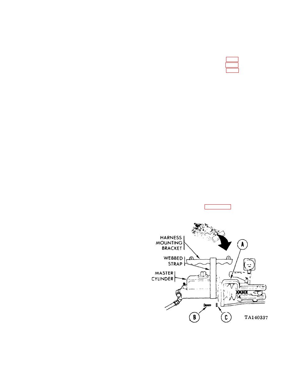
REMOVAL:
NOTE
For ease of access, you may drop
driver's
escape
hatch
(TM
9-2350-222-10) and remove three
fire extinguisher cylinders (page
21-49).
1.
Install webbed strap firmly to support master
cylinder when bracket (A) has been removed.
NOTE
For easier removal, remove two
screws (B) at back side first,
2.
Using 9/16 inch socket or 9/16 inch wrench,
remove five screws (B) and lockwashers (C) from
bracket (A), Throw lockwashers away.
Go on to Sheet 2
13-29

