

TM 9-2350-222-20-1-5
BODY, ELBOWS, DELAY BOTTLE, AND RELATED TUBES REPLACEMENT (LATE MODEL)
(Sheet 6 of 7)
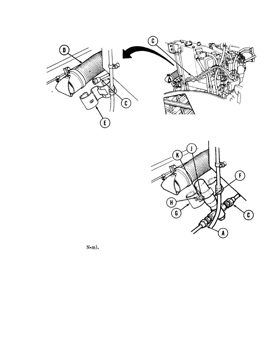
Install tube assembly (C) along left side of vehicle between heater hose (D) and delay bottle bracket (E)
3.
to driver's station.
Position delay bottle (F) onto bracket (G).
4.
Install strap (H) over delay bottle (F).
5.
Using 9/16 inch wrench, install and tighten
6.
bolt (J), nut, and lockwasher (K) to secure
strap (H) over delay bottle (F).
7.
Connect tube assembly (A) to delay bottle (F),
finger tight.
Using torque wrench and 1-1/4 inch crowfoot, tighten tube assembly (A) nuts at each end to
8.
40-55 lb-ft (54-75
9.
Connect tube assembly (C) to delay bottle (F), finger tight.
Go on to Sheet 7
Change 4
