TM 9-2350-222-20-1-5
HYDRAULIC PUMP DISCHARGE TUBE ASSEMBLY REPLACEMENT (Sheet 1 of 4)
PROCEDURE INDEX
PAGE
PROCEDURE
Removal
Cleaning and Inspection
Installation
Ratchet with 1/2 in. drive
TOOLS: 1-5/8 in. open end wrench
9/16 in. socket with 1/2 in. drive
1-1 1/16 in. open end wrench
10 in. extension with 1/2 in. drive
1-1/2 in. open end wrench
6 in. flat-tip screwdriver
9/16 in. combination box and
7/16 in. socket with 1/2 in. drive
open end wrench
SUPPLIES: Rags (Item 65, Appendix D)
Dry cleaning solvent (Item 54, Appendix D)
Engine oil (Item 43, Appendix D)
Drip pan
Lockwasher (MS35338-27) (4 required)
Lockwasher (MS35338-25) (2 required)
TM 9-2350-222-10
REFERENCES:
LO 9-2350-222-12
PERSONNEL: Two
PRELIMINARY PROCEDURES: Traverse turret placing boom over right front fender
(TM 9-2350-222-10)
Open turret platform access cover (TM 9-2350-222-10)
Disconnect battery ground straps (page 10-283)
Dump driver's seat (TM 9-2350-222-10)
Open front hull drain valve (TM 9-2350-222-10)
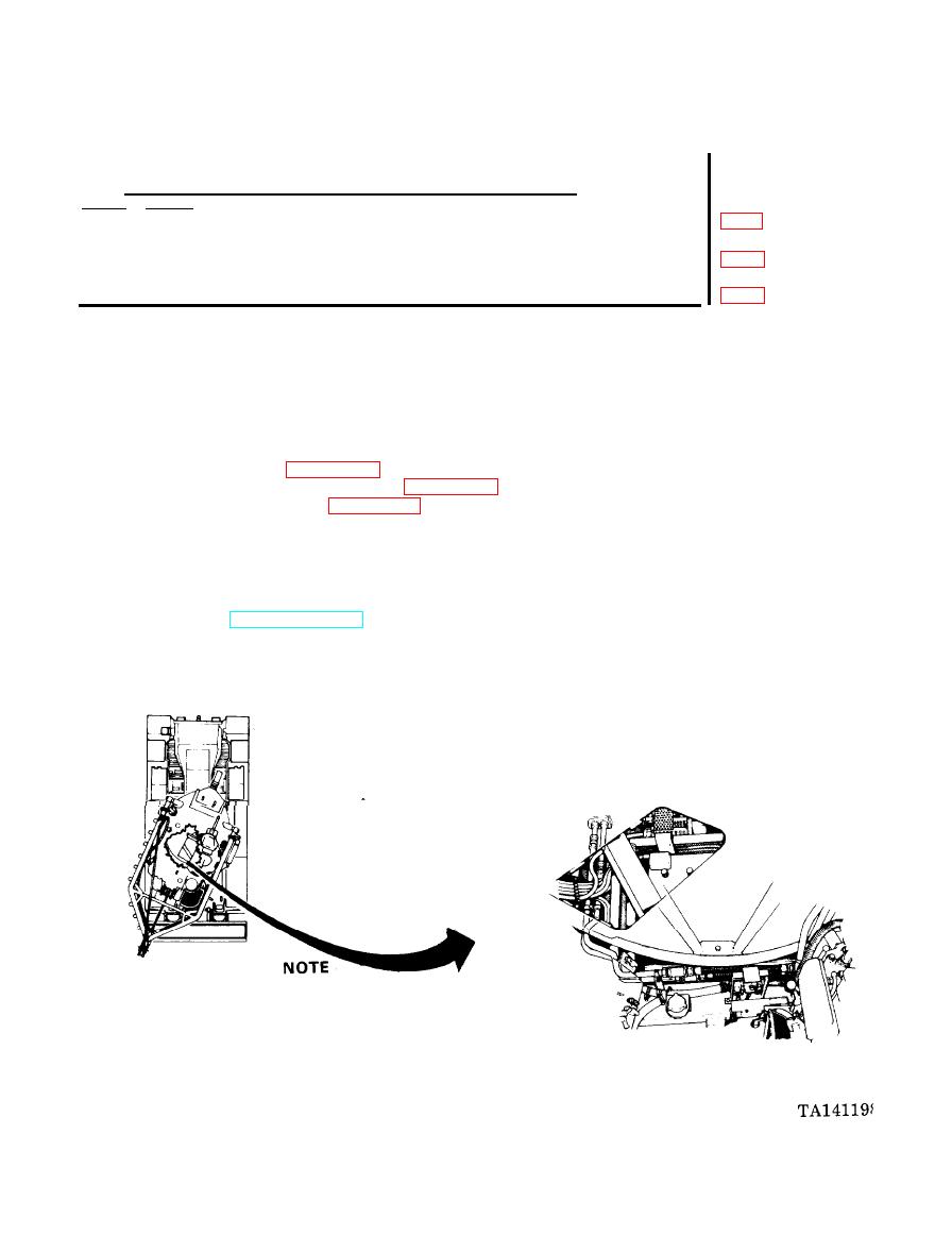
Traverse turret as needed during tube assembly removal and
installation. Removal and installation procedures for front and
rear hydraulic pump discharge lines are the same.
It is
necessary to remove front filter line to gain access to valve on
rear filter line.
Go on to Sheet 2


