

TM 9-2350-222-20-1-5
REAR DRAIN VALVE CONTROL LEVER ASSEMBLY REPLACEMENT (Sheet 4 of 4)
5.
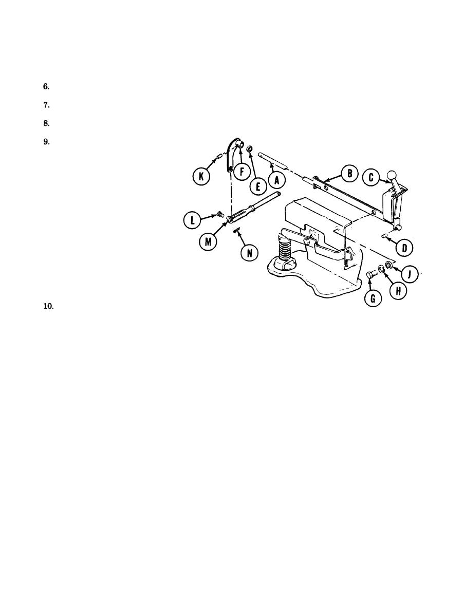
Clamp bracket (B) in vise.
Using 1/8 inch punch and pliers, line up hole in shaft (A) with hole in control lever (C).
Using pliers, start pin (D) in hole in control lever (C).
Using hammer and 1/8 inch punch, drive pin (D) all the way in hole.
Position bracket (B) in vehicle.
NOTE
lt may be necessary to tap lever
(F) with hammer for installation.
Install washer (E) and lever (F) on shaft (A).
11.
Using wrench, install two screws (G), new lockwashers (H), and flat washers (J) attaching bracket
(B) to vehicle.
12.
Using 1/8 inch punch, line up hole in shaft (A) with hole in lever (F).
13.
Using pliers, stars pin (K) in hole in lever (F).
14.
Using hammer and 1/8 inch punch, drive pin (K) all the way in hole.
15.
Install clevis pin (L) through hole in clevis (M) and hole in lever (F).
16.
Install new cotter pin (N) in clevis pin (L).
17.
Operate rear drain valve and make sure valve opens and closes smoothly. If valve does not open
and close properly, check for things in the way and for missing parts. Clear things in the way and
isntall missing parts.
18.
Place driver's seat to normal position (TM 9-2350-222-10).
End of Task
TA140761
16-149
