TM 9-2350-222-20-1-4
STEERING CONTROL LINKAGE ADJUSTMENT (Sheet 8 of 13)
35. Attempt to insert locating pin (V).
-
36. If locating pin (V) can be inserted with
locating pin (P) inserted, go to step 46.
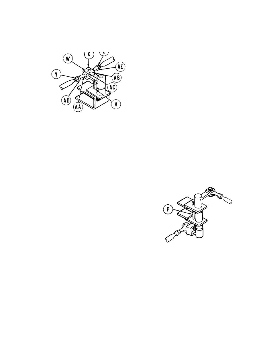
37. If locating pin (V) cannot be inserted with
locating pin (P) inserted, remove locating pin
(P) and use 9/16 inch wrench to remove
screws (W) and (X).
38. Using 9/16 inch wrench, loosen jamnuts (Y)
and (Z).
DRIVER'S STATION
LEFT REAR
39.
Remove steering rod end bearings (AA) and
(AB) from clevis (AC).
Insert locating pins (P) and (V).
40.
41.
Using 9/16 inch wrench on steering rod end
bearing flats (AD) and (AE), turn clockwise or
counterclockwise until screws (W) and (X) will
pass freely through steering rod end bearings
(AA) and (AB) and holes in clevis (AC).
Insert screws (W) and (X) finger tight through
42.
rod end bearings (AA) and (AB) and clevis (AC).
Remove locating pins (P) and (V).
43.
44.
U s i n g crowfoot wrench, adapter, and
t o r q u e wrench, tighten jamnuts (Y) and
( Z ) to 15-20 lb-ft (20-27 N-m).
Using torque wrench with socket, torque
45.
screws (W) and (X) to 15-20 lb-ft (20-27 N-m).
DRIVER'S STATION-
LEFT FRONT
Go on to Sheet 9
Change 5 15-9


