

TM 9-2350-222-20-1-4
TRACK ASSEMBLY REPLACEMENT (Sheet 9.3 of 10)
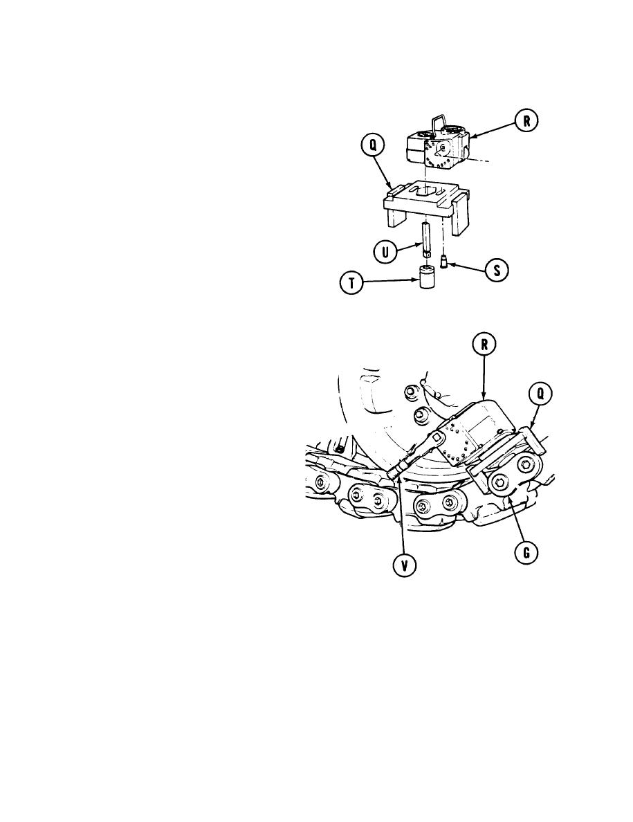
54. Fasten adapter (Q) to torque pack (R) using
shoulder screw (S).
55. Place 15/16 inch socket (T) on drive bar
(U) and install drive bar (U) into torque
pack (R).
Position torque pack (R) with adapter (Q)
56.
drive bar (U), and socket (T) over nut on end
connector (G) to be tightened. Ensure adapter
(Q) legs are seated firmly against shoe
assemblies on either side.
57.
rotate ratchet until socket (T) engages nut
on end connector (G).
Rotate ratchet (V) clockwise until torque
58.
pack dial indicates 180-200 lb-ft (244-
271 N-m).
Wait approximately 15 seconds, read
59.
dial, and repeat step 58 until dial reading
stabilizes at 180-200 lb-ft (244-271
N-m).
Rotate ratchet (V) counterclockwise
60.
until dial reading indicates 0. Remove
torque pack.
Repeat steps 56 thru 60 to tighten
61.
inboard end connector.
Remove 15/16 inch socket (T) from
62.
torque pack (R).
Go on to Sheet 10
14-90.2 Change 5
