

TM 9-2350-222-20-1-4
COMPENSATING IDLER ARM ASSEMBLY REPAIR (Sheet 5 of 5)
7.
Remove replacer from upper spindle.
8.
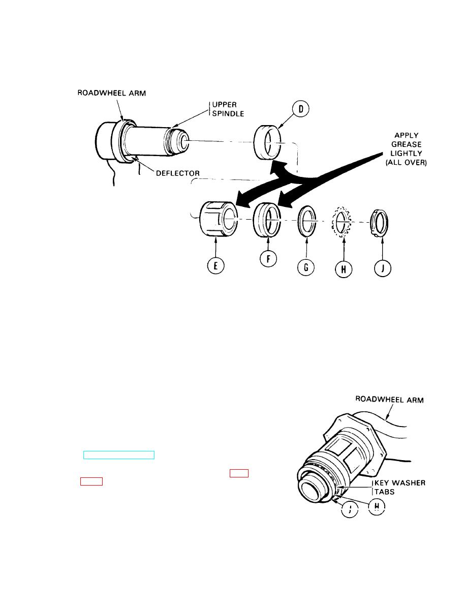
Apply light coat of grease to outer bearing (D), bearing spacer (E), and inner bearing (F). Install
them on arm upper spindle.
9.
Install bearing washer (G), key washer (H) with tabs toward nut (J), and screw nut (J) onto end of
upper spindle.
10.
Using spanner wrench (Item 25, Chapter 3, Section I), tighten nut (J) until bearing assembly
cannot be turned.
11.
Back nut (J) off just enough so bearing assembly can be turned by hand through one complete
turn on spindle.
12.
Using hammer and punch, bend tab of key
washer (H) so it fits in one of four slots in nut
(J).
13.
Service hub and arm assembly
(LO 9-2350-222-12).
14.
Install compensating idler arm assembly (page
End of Task
TA141353
Change 1 14-71
