TM 9-2350-222-20-1-4
GREASE ACTUATED TRACK ADJuSTING LINK REPLACEMENT (Sheet 3 of 7)
WARNING
Be cereful when lifting compensating idler
wheel hub (H). Serious injury to personnel
can result from careless handling.
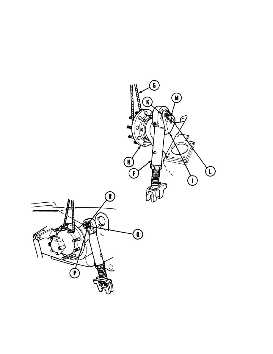
Attach sling assembly (G) to compen-
4.
sating idler wheel hub (H). Using lifting
device, raise compensating idler arm
(J) until adjusting link mounting eye
(K) is positioned above the front slope
.
Position adjusting link (F) as shown.
5.
Using 3/4 inch wrench, remove cap-
6.
screw (L) and lockwasher securing tab on
pin assembly (M) to inner face of com-
pensating idler arm (J). Throw lock-
washer away.
Using slip joint pliers, straighten and
7.
remove cotter pin (p). Throw pin away.
Using 1-1/8 in. socket, remove nut (Q) and
8.
W a s h e r (R).
Go on to Sheet 4
TA249135
Change 3
14-62.4


