

TM 9-2350-222-20-1-4
BRAKE CONTROL PEDAL AND BRACKET REPAIR AND REPLACEMENT (Sheet 1 of 5)
PROCEDURE INDEX
PAGE
PROCEDURE
Removal
Disassembly
Assembly
Installation
TOOLS: Hammer
3/16 in, drive punch
9/16 in. combination box and open end wrench
3/8 in. combination box and open end wrench
Vise
Alining punch
Slip joint pliers
SUPPLL ES: Spring pins (MS39086-47) (2 required)
Bearing (70417-A742-2) (5 required)
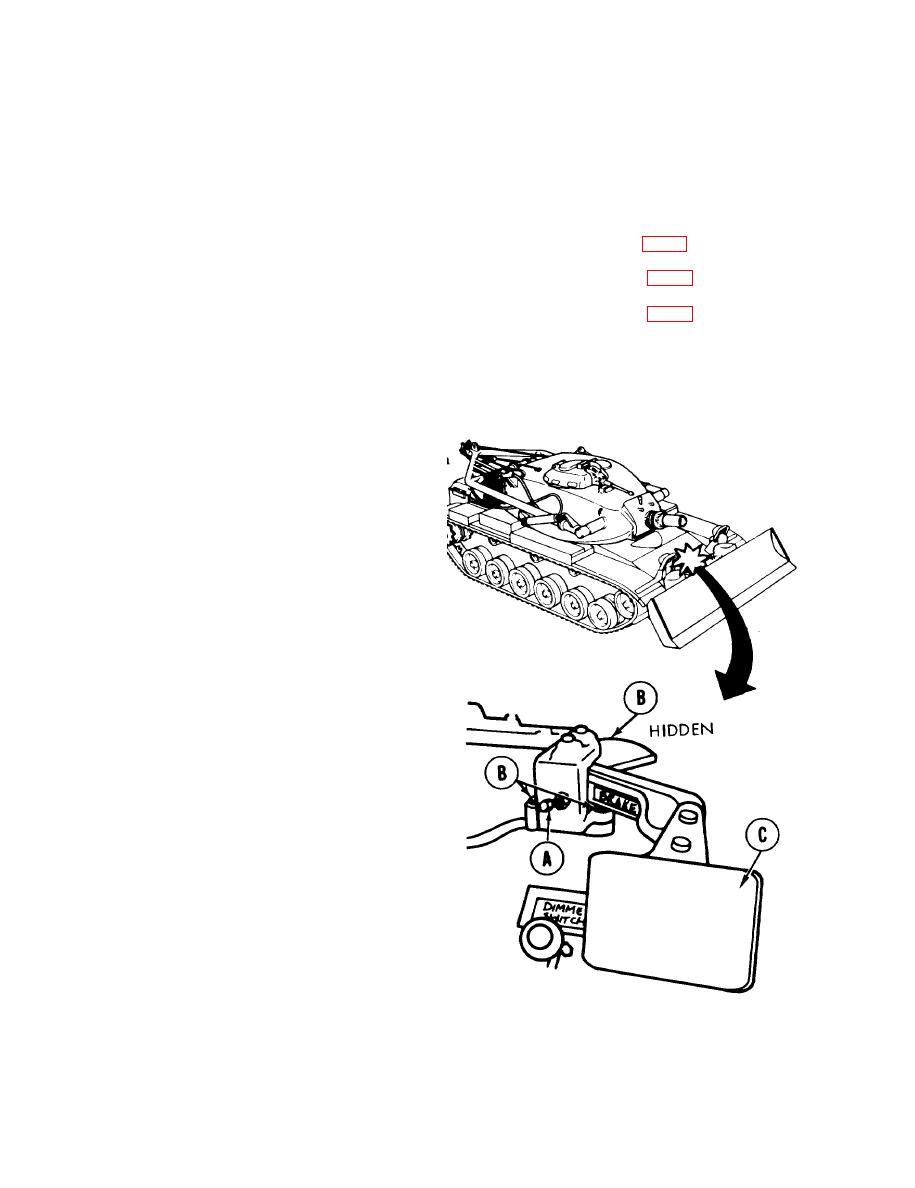
REMOVAL:
Using 3/8 inch wrench, remove screw (A).
1.
NOTE
Screw and washer (B) in rear mount-
ing hole may not come out of bracket
until later in disassembly.
Using 9/16 inch wrench, remove three
2.
mounting screws and lockwashers (B).
Raise and remove control pedal (C) and related
3.
parts as an assembly.
TA140332
Go on to Sheet 2
13-24

