

TM 9-2350-222-34-1
TRANSMISSION REPLACEMENT (Sheet 19 of 24)
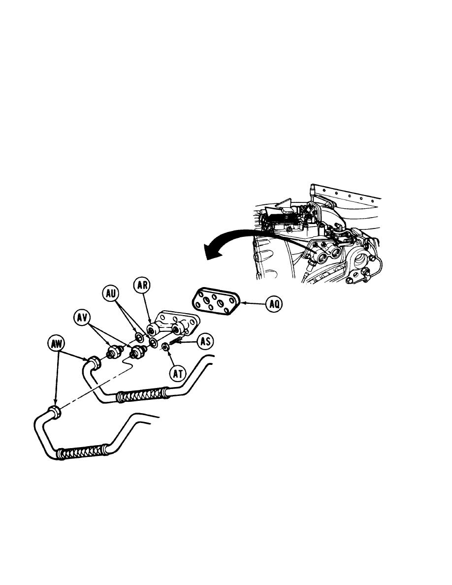
NOTE
Adapter (AR) must be positioned
properly.
Left side adapter has
threaded hole for thermostatic switch
which is angled downward. Right
side adapter has threaded hole of oil
temperature sensor angled upward.
41. On right side of transmission position gasket
(AQ) and adapter (AR) on studs (AS).
42. Using 9/16 inch socket, install six nuts (AT) on
studs (AS).
43. On left side of transmission, position gasket
(AQ) and adapter (AR) onto studs (AS).
44. Using 9/16 inch socket, install four nuts (AT)
onto studs (AS). Do not install nuts on two studs
located at top right side of adapter (AR).
NOTE
The procedures described in steps 46
and 46 apply to the left and right side
of transmission.
45. Position metallic gaskets (AU) into adapter (AR) and, using 1-5/8 inch wrench, install adapters (AV) into adapters
(AR).
46. Using 1-1/2 inch wrench, install tubes (AW) onto adapters (AV).
Go on to Sheet 20
TA130708
6-40
