TM 9-2350-222-34-1
HULL POWER WIRING HARNESS ASSEMBLY REPLACEMENT (Sheet 12 of 14)
NOTE
Steps 16-21 only for vehicles equipped as shown.
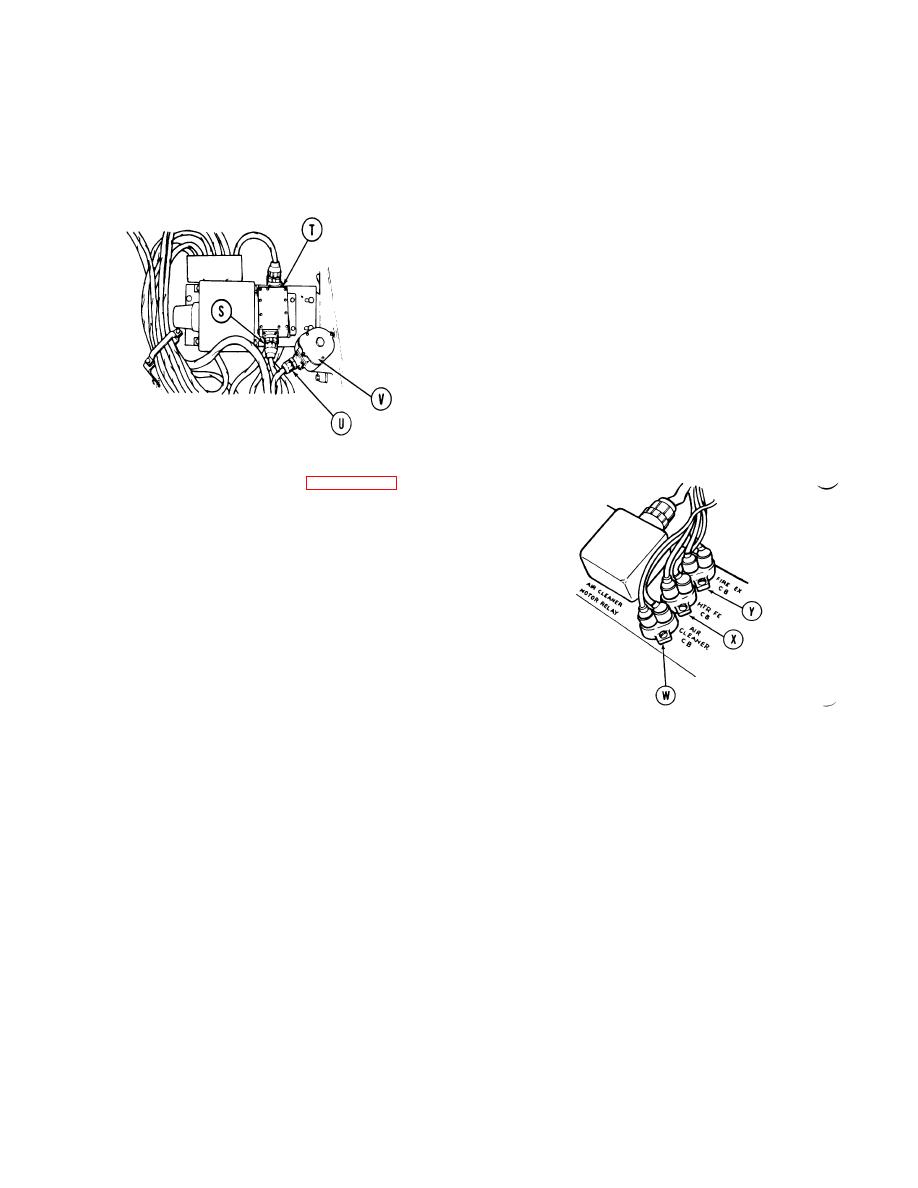
16. Using spanner wrench, connect connector (S) (CKT
81-5) to master relay solenoid (T).
17. Using 1-1/8 inch wrench, connect connector (U) to
voltage adjusting rheostat control box (V).
18. Apply silicone compound (Item 10, Appendix B) to all
male connectors.
19. Connect two connectors (CKT 415) to air cleaner
circuit breaker (W).
20. Connect two connectors (CKT 400-459) to heater
feed circuit breaker (X).
21. Connect two connectors (CKT
975)
to
fire
extinguisher circuit breaker (Y).
Go on to Sheet 13
TA130613
5-34


