TM 9-2350-222-20-2-3-2
36-28. SAFETY SWITCH AND GUARD INSTALLATION PROCEDURE (CONT)
Procedure
NOTE
Check that mark with masking tape made at removal
top.
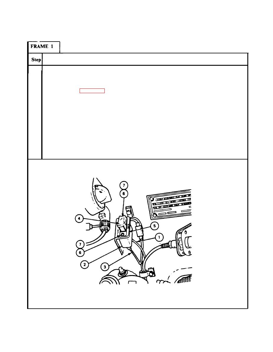
Connect circuit 111 power lead connector (1) of wiring harness (10911240) to safety
1.
switch (2) (JPG).
Connect trigger switch lead connector (3) of wiring harness (10884158) to safety switch
2.
(2) (JPG).
3.
Place safety switch (2) and guard (4) in mounting position in switch bracket (5).
4.
Using screwdriver, install two screws (6) and two lockwashers (7) through switch guard
(4), bracket (5) and into safety switch (2).
END OF TASK
Para 38-28 Cont
36-65


