

CONTROL VALVE ASSEMBLY REPLACEMENT (Sheet 12 of 12)
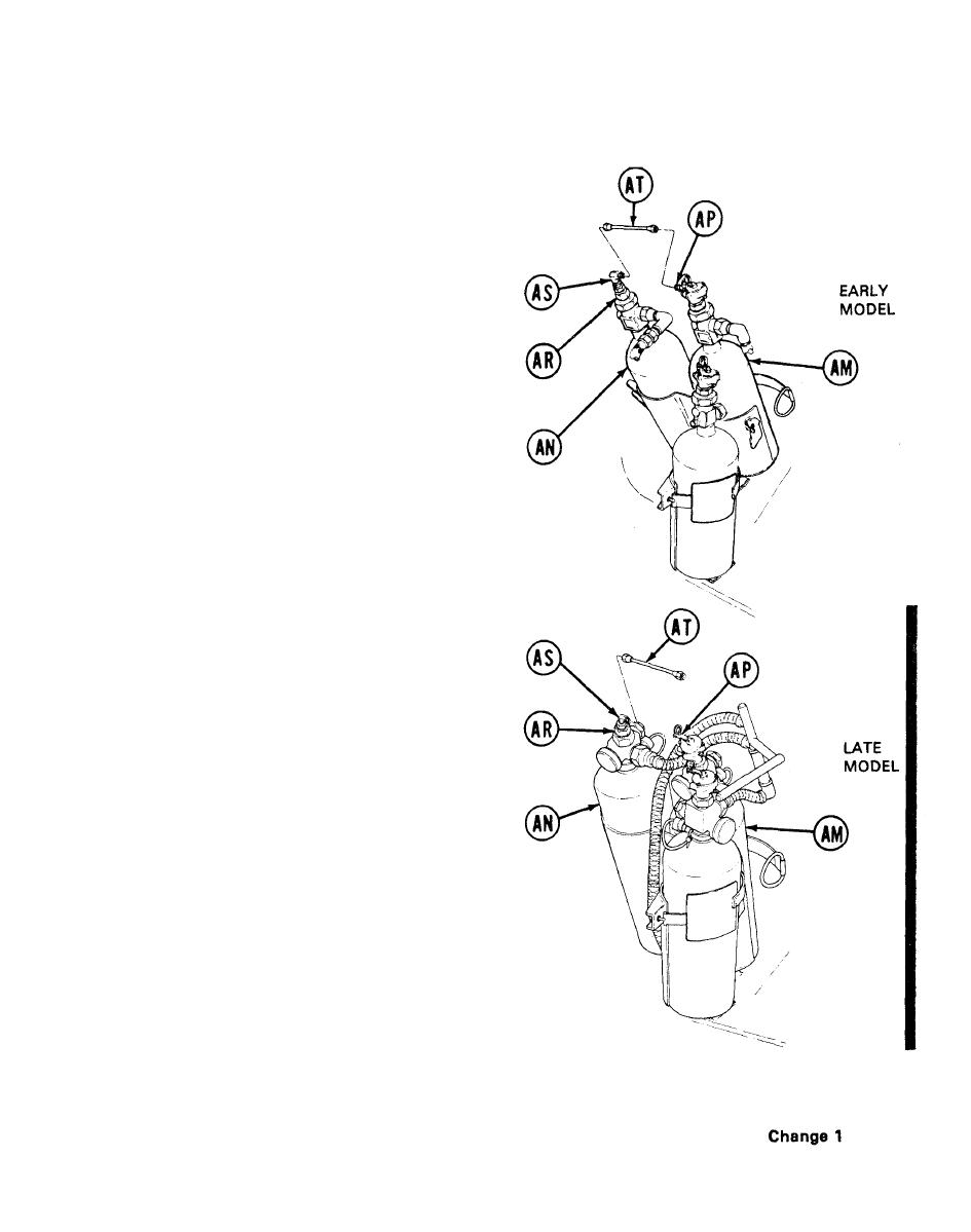
29. Using 8 inch adjustable wrench, install elbow (AS) into head (AR). Using 3/8 inch drive torque wrench
and 1/2 inch crowfoot (Item 36, Chapter 3, Section I), tighten elbow (AS) to 135-150 lb-in (15.3 -17.0
N m). During tightening, attempt to aline elbow (AS) for later installation of tube (AT).
30. Using 9/16 inch wrench, install tube (AT)
onto elbow (AS). Using 3/8 inch drive torque
wrench and 9/16 inch crowfoot (Item 37,
Chapter 3, Section I), tighten connector on
tube (AT) to 135-150 lb-in (15.3 -17.0 N m).
31. Using 9/16 inch wrench, install tube (AT)
onto adapter (AP). Using 3/8 inch drive
torque wrench and 9/16 inch crowfoot (Item
37, Chapter 3, Section I), tighten connector
on tube (AT) to 135-150 lbin (15.3-17.0 N m).
32. If cylinder strap is loosened, secure cylin-
ders (AM) and (AN, with strap attached to
mounting bracket.
33. Perform semiannual functional checkout
(page 3-52).
End of Task
TA253902
21-47
