

TM 9-2350-222-20-1-5
TM 9-2350-222-20-1-5
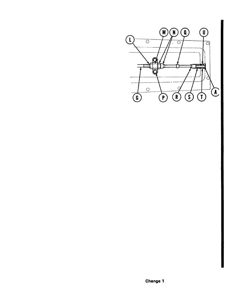
GENERATOR EXHAUST VALVE AND CONTROL CABLE REPLACEMENT (Sheet 6 of 6)
Install nut (L) and support (M) over end at
9.
control cable (G).
Install shakeproof washer and nut (N) over
10.
end of control cable (G). Holding support (M)
with 1 in. wrench, tighten nut (N) with 15/16
wrench.
Using 9/16 inch wrench, install two screws
11.
and new lockwashers (P) to secure support
(M) to front access cover.
Install seals (Q) onto control cable (G).
12.
Install nut (R) on control cable (G).
13.
Install clevis (S) on control cable (M). Adjust clevis (S) to aline holes in clevis (S) with holes in
14.
generator exhaust valve (A).
Install new cotter pin (U) through pin (T). Use pliers and bend ends of cotter pin.
16.
Using pliers and 7/16 inch wrench, tighten nut (R) against clevis (S).
17.
18. Check that clevis (S) is centered and does not bind against sides of lever of generator exhaust valve (A).
Install engine shroud (page 9-3).
19.
Install air intake (page 7-85).
20.
TA253856
End of Task
19.1-13/ (19.1-14 Blank)
