

TM 9-2350-222-20-1-5
HYDRAULIC PUMP VALVE AND ASSOCIATED LINES REPLACEMENT (Sheet 11 of 11)
Using appropriate wrenches, tighten all tube and hose assembly nuts that were connected in steps
42.
8, 9, 10, 11, 24, 25, 27, 29, 32, 33, 34, 35, a n d 36.
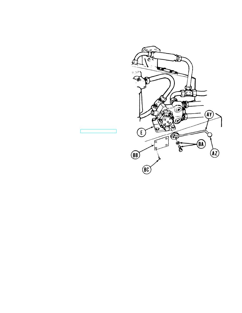
Coat threads of handle (AY) with adhesive
43.
(Item 2, Appendix D) and install knob (AZ).
Position handle (AY) onto valve (E).
44.
Using 9/16 inch socket, install two screws and
45.
washers (BA) to secure handle (AY) to valve (E).
Position instruction plate (BB) to reservoir.
46.
Using hammer, install four drive screws (BC) to
secure instruction plate.
Install driver's seat assembly (page 17-43).
47.
Install three fire extinguisher cylinders and
48.
lines (page 21-50).
Fill hydraulic reservoir (LO 9-2350-222-12).
49.
End of Task
TA141157
18-55
