

TM 9-2350-222-20-1-4
SHIFT LINKAGE ADJUSTMENT (Sheet 17 of 20)
127. Install 2A powerplant (page 5-14) or 2D
powerplant (page 5-37).
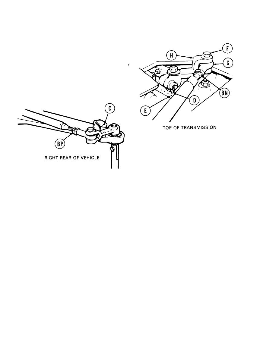
128. At top of transmission, try to insert locating pin
in alinement hole (C). If locating pin can be
inserted, go on to step 129. If locating pin
cannot be inserted, go to step 130.
129. At top of transmission, check position of
shifting position indicator (D). If shifting
position indicator (D) is pointing to most
forward dot (E), linkage is in adjustment. Go
to step 160. If shifting position indicator (D)
is not pointing to most forward dot (E), go on
to step 130.
130. Using 9/16 inch wrench, loosen jamnuts (BN)
and (BP).
131. Using 9/16 inch wrench, remove screw (F) (if not removed in step 4).
132. Using hands, move shifting position indicator (D) to most forward dot (E).
133. Insert locating pin in alinement hole (C) (if not inserted in step 128).
NOTE
It may be necessary to move shifting position indicator (D) to
most rear dot to adjust shifting rod bearing end (G) and then
back to most forward dot (E) to check adjustment in step 134.
134. Using 9/16 inch wrench, adjust shifting rod bearing end (G) by turning clockwise or
counterclockwise until screw (F) drops freely through shifting rod bearing end (G) and clevis (H).
Go on to Sheet 18
TA139271
11-18
