TM 5-5420-226-20-1
DETAILED
TROUBLESHOOTING
PROCEDURE
Symptom-39
INDICATOR
- GAGE
FUEL
LEVEL
GAGE
WILL
NOT
WORK
(ALL
OTHER
GAGES
WORK).
I
\
NOTE
1
This procedure
is to be performed
by
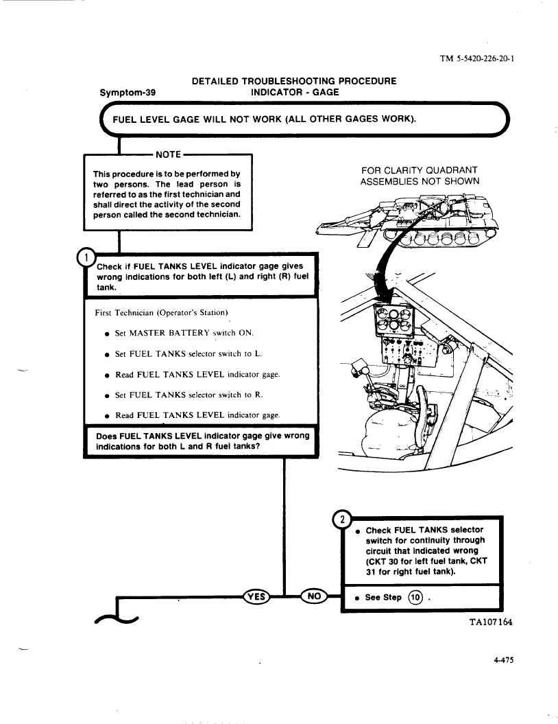
FOR CLARITY
QUADRANT
two
persons.
The
lead
person
is
ASSEMBLIES
NOT SHOWN
referred
to as the first technician
and
shall direct the activity of the second
person called the second technician.I
-.
.
I
~
Check if FUEL TANKS
LEVEL indicator
gage gives
wrong
mdlcatlons
for both left (L) and right (R) fuel
First
Technician
(Operator’s
Station)
l Set MASTER
BATTERY
switch
ON.
l Set FUEL
TANKS
selector
switch
to L.
l Read FUEL
TANKS
LEVEL
indicator
gage.
l Set FUEL
TANKS
selector
switch
to R.
l Read FUEL
TANKS
LEVEL
indicator
gage.
Does
FUEL TANKS
LEVEL
indicator
gage give wrong
indications
for both L and R fuel tanks?
m
( )
l Check FUEL TANKS selector
switch for continuity
through
circuit that indicated
wrong
(CKT 30 for left fuel tank, CKT
31 for right fuel tank).
l See Step
@
.
TA107164
4-475

