TM 5-5420-226-20-1
Symptom-37
DETAILED
TROUBLESHOOTING
PROCEDURE
INDICATOR
- GAGE
BATTERY/GENERATOR
GAGE
POINTER
IN RIGHT
RED
AREA.
~
NOTE
Units with STE/lCE
perform
Test No.
67, Charging Circuit and Battery Volt-
age
Test.
Units
without
STE/lCE
proceed
to Step
1
.
/W~th
engine
running,
check
voltage
output
at slave
receptacle.
Technician
(Operator’s
Station)
l Set MASTER
BATTERY
switch
OFF.
Technician
(Commander’s
Station)
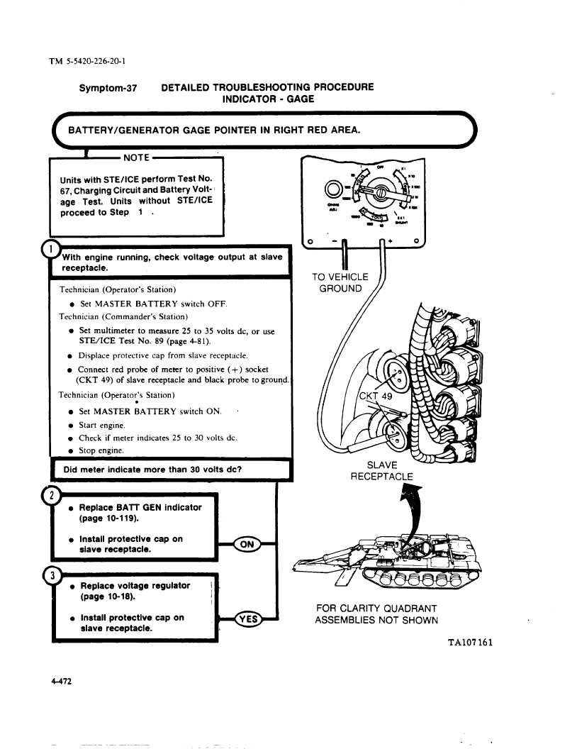
l Set multimeter
to measure
25 to 35 volts dc, or use
STE/ICE
Test No. 89 (page 4-81).
l Displace protective
cap from slave receptacle.
l Connect
red probe
of meter
to positive
( + ) socket
(CKT
49) of slave receptacle
and black
probe
to ground.
Technician
(Operator’s
Station)
l
l Set MASTER
BATTERY
switch
ON.
.
l Start engine,
l Check if meter indicates
25 to 30 volts dc.
l Stop engine.
I
Did meter
indicate
more than 30 volts dc?
l Replace
BA~
GEN indicator
(page
10-119).
l Install protective
cap on
siave receptacle.
l Replace
voltage
regulator
i
(page
10-18).
l Install protective
cap on
siave receptacle.
I
w
TO VEHICLE
GROUND
1
RECEPTACLE
FOR CLARITY
QUADRANT
Assemblies
NOT SHOWN
TA107161
4-472