

TM 9-2350-222-20-1-5
DRIVER'S SEAT ADJUSTING ASSEMBLY REPAIR (Sheet 3 of 10)
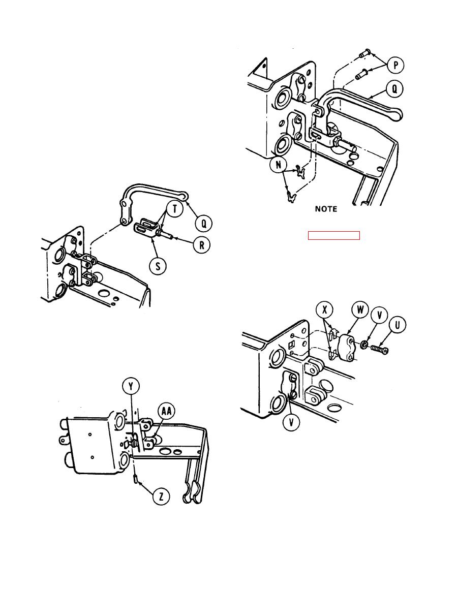
8. Using pliers, remove two washers (N).
9. Using pliers, remove two pins (P) from handle
(Q).
10. Remove handle (Q).
11. Remove link (R) and clevis (S).
12. Using two 9/16 inch wrenches, remove nuts (T)
from link (R) and clevis (S).
Use pencil and masking tape
(Item 57, Appendix D) to tag
shims
(X)
and
housing
assemblies (W) as they are
removed to make sure they are
replaced in the exact location
during installation.
13.
Using flat-tip screwdriver, remove eight screws
(U), eight lockwashers (V), four housing
assemblies (W), and shims (X). Throw
lockwashers away.
14. Using flat-tip screwdriver, carefully pry
washer (Y) away from bracket. Using 1/8
inch punch and pliers, remove pin (Z) from
adjusting pin (AA).
Go on to Sheet 4
TA139226
17-25

