

TM 9-2350-222-20-1-4
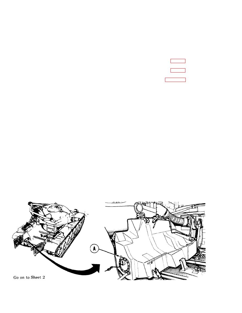
CAPACITOR AND HOUSING ASSEMBLY REPLACEMENTT, LEFT FUEL TANK
(Sheet 1 of 6)
PROCEDURE INDEX
PAGE
PROCEDURE
Removal
Cleaning and Inspection
Installation
1/2 in. socket with 1/2 in. drive
TOOLS: Flat-tip screwdriver
Ratchet with 1/2 in. drive
Diagonal cutting pliers
Torque wrench with 3/8 in. drive
Putty knife
(0-200 lb-in) (0-22 N.m)
Slip joint pliers
1/2 in. socket with 3/8 in. drive
Gasket (2 required
SUPPLIES: Dry cleaning solvent (Item 54,
Gasket
Appendix D)
Lockwasher (4 required)
Rags (Item 65, Appendix D)
Lockwire (Item 60, Appendix D)
Lockwasher (4 required)
PRELIMINARY PROCEDURES: Remove powerplant (page 5-1)
Isolate left fuel tank (TM 9-2350-222-10)
Drain left fuel tank (page 7-125)
NOTE
Your vehicle may have the capacitor and housing assembly mounted
with connector facing up. When installing the capacitor and housing
assembly, be sure to install it so the connector faces down.
REMOVAL:
1.
Using hands, remove electrical connector (A) from mating connector.
10-396 Change 5

