TM 9-2350-222-20-1-5
LEFT DISCHARGE VALVE, TUBES, AND RELATED PARTS REPLACEMENT (FIXED FIRE
EXTINGUISHER) (Sheet 5 of 5)
NOTE
When installing clamps in step 2, position clamps down.
2.
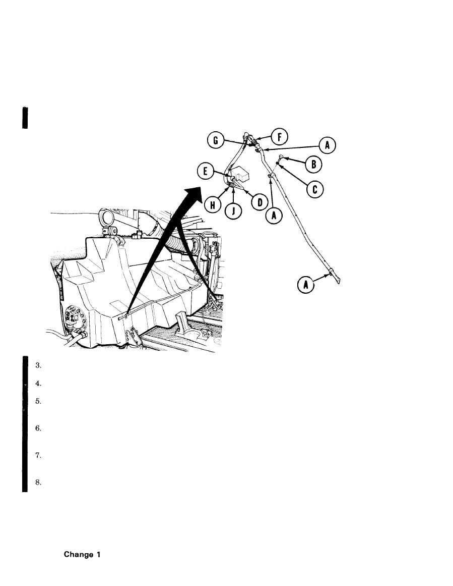
Using socket loosely install three clamps (A), screws (B), and new lockwashers (C), securing line to
left fuel tank. (Clamps must remain loose for positioning during installation.)
Using 7/8 and 1-1/8 inch wrench, install connector on tube (D) to elbow (E) and tighten.
Using socket, tighten three screws (B) securing clamps (A) to fuel tank.
Holding adapter (F) with 3/4 inch wrench and using 7/8 inch wrench, tighten connector (G) onto
adapter (F).
If tube (H) was installed to tube (D) with adapter (J), use two 1-1/8 inch wrenches to tighten
connection.
If tube (H) was installed to tube (D) without adapter (J), use two 7/8 inch wrenches to tighten
connection.
Install 2A powerplant (page 5-14) or 2D powerplant (page 5-37).
End of Task
TA253759
21-80


