

TM 9-2350-222-20-1-5
TUBE ASSEMBLY 1ST SHOT CYLINDER LINE REPLACEMENT (Sheet 2 of 3)
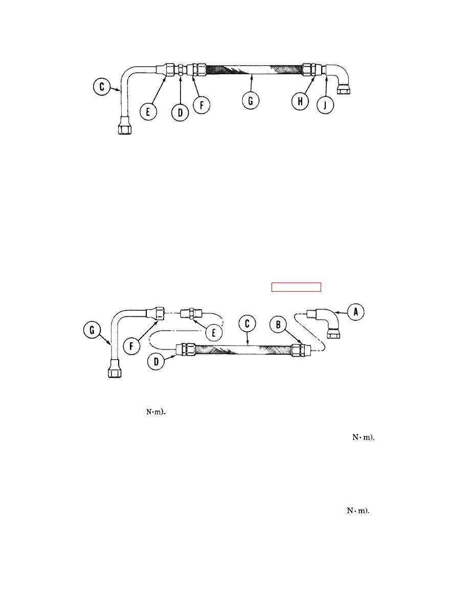
NOTE
Position tube and fitting in vise as necessary to accomplish
disassembly and assembly.
3.
Using 1-1/16 inch wrench to hold nipple (D), use 1-1/4 inch wrench on connector (E) and remove tube
(C) from nipple (D).
4.
Using 1-1/4 inch wrench to hold connector (F), use 1-1/16 inch wrench and remove nipple (D) from
hose (G).
5.
Using 1-1/4 inch wrench to hold connector (H), use pipe wrench and remove elbow (J) from hose
(G).
INSTALLATION:
NOTE
Apply zinc chromate primer (Item 50, Appendix D) to threads
prior to installation of threaded tube/hose connectors.
Using pipe wrench to hold elbow (A), use 1-1/4 inch wrench on connector (B) and install
1.
hose (C) onto elbow (A). Then, using torque wrench and 1-1/4 inch crowfoot, tighten to
70-90 lb-ft (95-122
2.
Using 1-1/4 inch wrench to hold connector(D) and 1-1/16 inch wrench on nipple (E), install nipple (E).
Then, using torque wrench and 1-1/4 inch crowfoot, tighten to 70-90 Ib-ft (95-122
NOTE
Be sure tube (G) is positioned as shown above when connector
(F) is tightened.
Using 1-1/16 inch wrench to hold nipple (E) and 1-1/4 inch wrench on connector (F), install tube (G).
3.
Then, using torque wrench and 1-1/4 inch crowfoot, tighten to 40-50 lb-ft (54-68
Go on to Sheet 3
Change 4
