

TM 9-2350-222-20-1-4
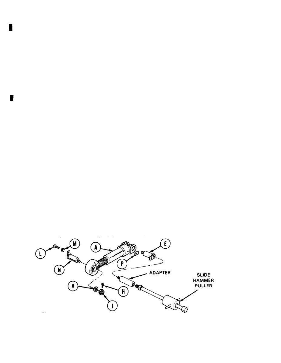
MECHANICAL TRACK ADJUSTING LINK REPLACEMENT (Sheet 3 of 5)
5.
Go to other end of adjusting link (A).
6.
Using pliers, straighten cotter pin (H) and remove it from slotted nut (J). Throw cotter pin away.
7.
Using 1-1/8 inch socket with ratchet, loosen nut (J).
8.
Remove nut (J) and washer (K).
Using 3/4 inch socket, remove screw (L). Remove lockwasher (M). Throw lockwasher (M) away.
9.
10.
Pick up nut (J) and screw it a couple of turns onto pin (N).
Using hammer, tap nut (J) on pin (N) to loosen pin (N).
11.
12.
Screw adapter into end of pin (E). Screw end of slide hammer puller (Item 12, Chapter 3, Section
1) into adapter (Item 7, Chapter 3, Section I) and, using slide hammer puller, remove pin (E) and
shim (P) from link (A).
13.
Using second person to hold link (A), rotate arm so that pin (N) will be over front slope of tank.
14.
Remove nut (J) from pin (N).
NOTE
Have third person hold link when pin (N) is removed.
NOTE
Use caution when removing pin (N) because link (A) may fall
away.
Using pry bar, remove pin (N) from link (A).
15.
16.
Remove link (A) from tank. Lower idler arm to normal position.
NOTE
If pin (N) is hard to remove, screw adapter onto pin (N). Screw
end of slide hammer puller into adapter and use slide hammer
puller to remove pin (N) from link (A).
TA249127
Go on to Sheet 4
14-58
Change 3
