TM9-2350-222-20-1-3
FUEL-WATER SEPARATOR OPERATIONAL TESTS (2D ENGINE) (Sheet 5 of 11)
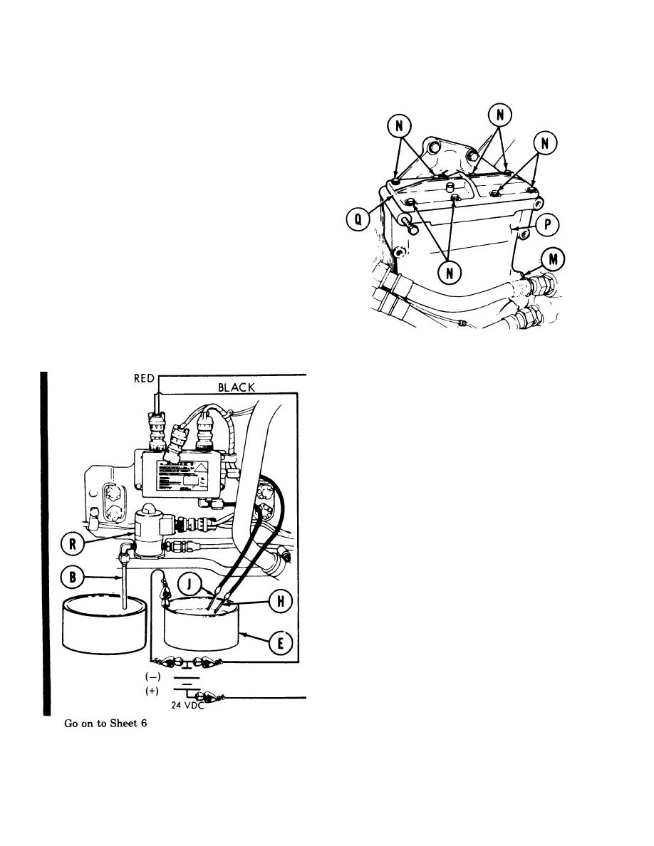
Using adjustable wrench, loosen pipe plug in
7.
upper sensor hole enough to allow fuel to leak.
Check to see if fuel leaks from upper sensor
8.
hole (M).
If fuel does not leak from upper sensor hole
9.
(M), remove pipe plug from upper sensor hole
(M) and go on to step 10. If fuel does leak from
upper sensor hole (M), use adjustable wrench to
tighten pipe plug in upper sensor hole (M) and
go to step 14.
CAUTION
B e very careful not to disturb
center filter element. Center filter
element m u s t b e r e p l a c e d i f
disturbed in any way.
10. Using 7/16 inch wrench, remove eight screws,
lockwashers, and flat washers (N) securing cover
to separator (P). Remove cover (Q) from
separator (P). Throw lockwashers away.
11.
Add fuel to fuel-water separator (P) until fuel
leaks from upper sensor hole (M).
Using adjustable wrench, install pipe plug
12.
into upper sensor hole (M).
Place cover (Q) in position and, use 7/16 inch
13.
wrench, install eight screws, lockwashers, and
flat washers (N).
14.
Hold tips of upper (H) and lower (J) sensor
proves in water in metal container (E).
NOTE
Remove both upper (H) and
lower (J) sensor probes from
water in metal container (E) as
soon as fluid begins draining
from drain tube (B).
Listen for solenoid drain valve (R) to click
15.
and watch for fluid to begin draining from
solenoid drain valve drain tube (B).
If fluid does not begin draining, refer to
16.
troubleshooting procedures (see page 4-1).
If fluid does begin draining, go on to
17.
15-second drain test on next page.
TA253316
7-270 Change 1


