TM
5-5420-226-20-1
Symptom-72
DETAILED
TROUBLESHOOTING
PROCEDURE
STEPo1CONTINUED
SUPPORT
SYSTEM
- PERISCOPES
T
(Continued)
First
l
l
l
l
Technician
(Commander’s
Station)
Remove
floor
access
cover
(at Commander’s
feet)
(page
17-9).
Disconnect
front
accessories
harness
connector
(CKT
5 16) from
IR powerpack
input
connector
of defective
IR periscope.
Set multimeter
to measure
18 to 30 volts
dc, or use
STE/ICE
Test
No.
89 (page
4-81).
Connect
red probe of meter to front accessories
harness
connector
(CKT
5 16) and black
probe
to ground.
Second
Technician
(Operator’s
Station)
l
Set MASTER
BATTERY
switch
ON,
l
Set NIGHT
VISION
switch
ON.
First
Technician
(Commander’s
Station)
l
Check
if meter
indicates
18 to 30 volts dc.
Does meter
indicate
18 to 30 volts dc?
I
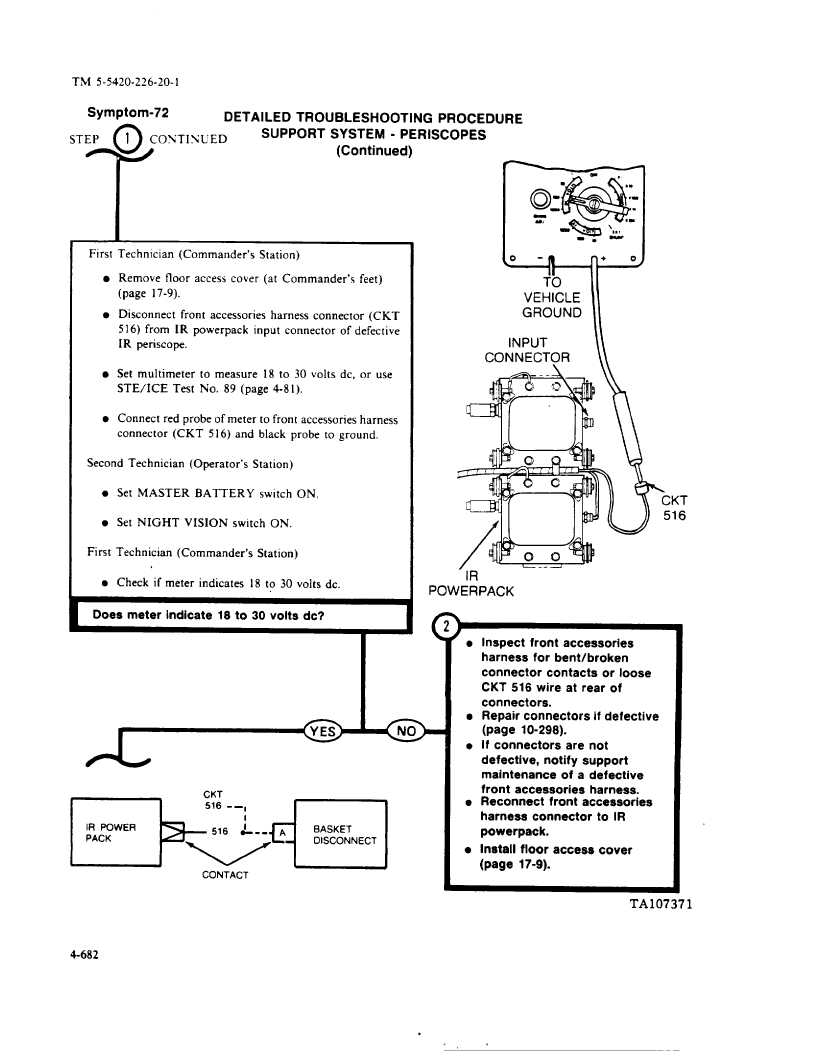
VEHICLE
GROUND
II
INPUT
CONNECT?R
\
~---A—
\
\
IR
POWER PACK
(
f
>~_._(fq
CONTACT
h
)
l
inspect
front accessories
harness
for bent/broken
connector
contacts
or loose
CKT 516 wire at rear of
connectors.
s
Repair connectors
if defective
(page
10-298).
l
if connectors
are not
defective,
notify
support
maintenance
of a defective
front accessories
harness.
l
Reconnect
front accessories
harness
connector
to iR
powerpack.
l
Instail
floor access
cover
(page
17-9).
4-682
.


