TM
5-5420-226-20-1
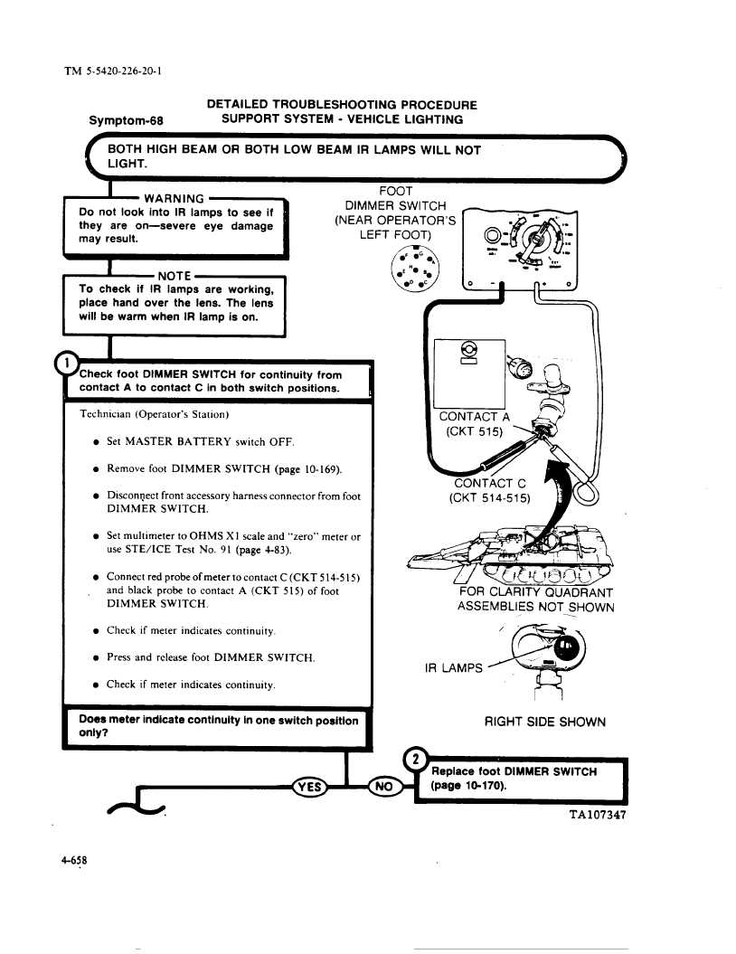
DETAILED
TROUBLESHOOTING
PROCEDURE
Symptom-68
SUPPORT
SYSTEM
- VEHICLE
LIGHTING
BOTH
HIGH
BEAM
OR BOTH
LOW
BEAM
IR LAMPS
WILL
NOT
1
Cnn-r
Go::;;:e4
Do not look into IR lamps
to see if
C:::==l
To check
if IR lamps
are
working,
place
hand
over
the lens. The lens
Iuul
DIMMER
SWITCH
m
(NEAR OPERATOR’S
. ‘
-
“,.
LEFT FOOT)
o-f
-“
.-
..
(7
-.
.-
lF 9G.,
\,,!
l
E ‘b
Bm
---
2
Check foot DIMMER
SWITCH
for continuity
from
contact
A to contact
C in both switch
positions.
Technician
(Operator’s
Station)
l Set MASTER
BATTERY
switch
OFF.
l Remove foot DIMMER
SWITCH
(page
10-169).
l Discorqect
front accessory
harness
connector
from foot
DIMMER
SWITCH.
l Set multimeter
to OHMS
X 1 scale and “zero”
meter or
use STE/ICE
Test
No. 91 (page 4-83).
l Connect red probe of meter to contact C(CKT
514-5
15)
and black
probe
to contact
A (CKT
5 15) of foot
DIMMER
SWITCH.
l Check if meter indicates continuity,
l Press and release foot DIMMER
SWITCH.
l Check if meter indicates continuity.
Does meter indicate
continuity
in one switch position
.
4-658
W~-!:”OJ
FOR CLARITY
QUADRANT
ASSEMBLIES
NOT SHOWN
. .
Z#)
/’.
:-””
-
IR LAMPS
‘
RIGHT
SIDE SHOWN
(page 10-170).