TM
5-5420-226-20-1
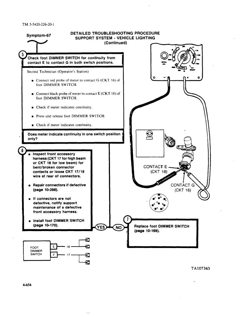
Symptom-67
DETAILED
TROUBLESHOOTING
PROCEDURE
SUPPORT
SYSTEM
- VEHICLE
LIGHTING
(Continued)
#check
foot
DIMMER
SWITCH
for continuity
from
contact
E to contact
G in both switch
positions.
Second
Technician
(Operator’s
Station)
Connec~
red probe of meter
to contact
G (CKT
16) of
foot DIMMER
SWITCH.
,Comtect black probe of meter to contact
E (CKT
18) of
foot DIMMER
SWITCH.
Check
if meter
indicates
continuity.
Press
and
release
foot DIMMER
SWITCH.
Check
if meter
indicates
continuity.
Does meter indicate
continuity
in one switch position
only?
‘e
l
l
Q
Inspect
front accessory
harness (CKT 17 for high beam
or CKT 18 for low beam)
for
bent/broken
connector
contacts
or loose CKT 17/18
wire at rear of connectors.
Repair connectors
if defective
(page
10-298).
If connectors
are not
defective,
notify
support
maintenance
of a defective
front accessory
harness.
Install foot DIMMER
SWITCH
(page
10-170).
FOOT
t=
E
l-k
DIMMER
SWITCH
F
‘7-
0YES
(
0NO
0
-n
n+
o
(CKT 16)
Replace
foot DIMMER
SWITCH
(page
10-169).
L
J
k
TA107343
4-654