TM
5-5420-226-20-1
(
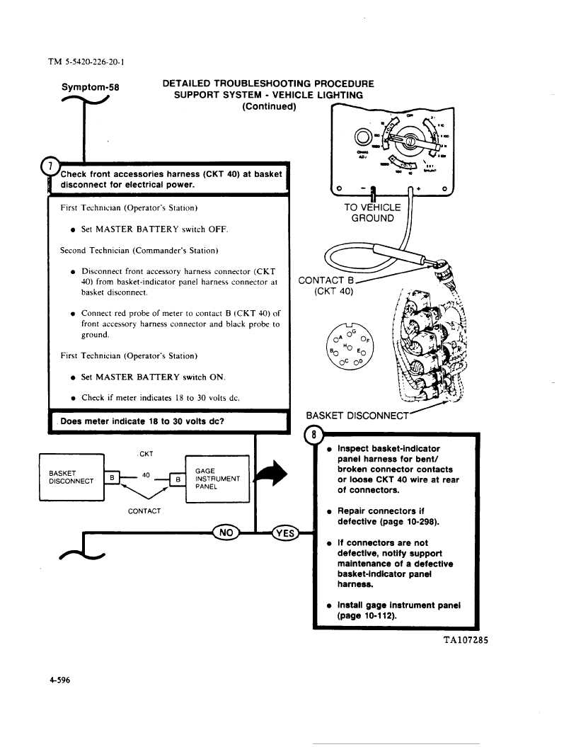
Symptom-58
DETAILED
TROUBLESHOOTING
PROCEDURE
T
SUPPORT
SYSTEM
- VEHICLE
LIGHTING
(Continued)
&
disconnect
for electrical
power.
1
First
Technw]an
(Operator’s
Station)
l Set MASTER
BATTERY
switch
OFF,
Second
Technician
(Commander’s
Station)
l Disconnect
front
accessory
harness
connector
(CKT
40) from
basket-indicator
panel
harness
connector
at
basket
disconnect.
l Connect
red probe of meter
to contact
B (CKT
40) of
front
accessory
harness
connector
and black
probe
to
ground,
First
Technician
(Operator’s
Station)
l Set MASTER
BATTERY
switch
ON.
l Check if meter indicates
18 to 30 volts dc,
/
Does meter
indicate
18 to 30 volts dc?
m
\
w,
BASKET
DISCONNECT-
=p’_...’_.+-’i
+
CONTACT
(
l Inspect
basket-indicator
panel
harness
for bent/
broken
connector
contacts
or loose
CKT 40 wire at rear
of connectors.
l Repair connectors
if
defective
(page
10-298).
l If connectors
are not
defective,
notify
support
maintenance
of a defective
basket-indicator
panel
harness.
l Install gage instrument
panel
(page
10-112).
TA107285
4-596