TM
5-5420-226-20-1
Svmntom-58
DETAILED
TROUBLESHOOTING
PROCEDURE
—.
r-–
T
SUPPORT
SYSTEM
- VEHICLE
LIGHTING
(Continued)
I
I
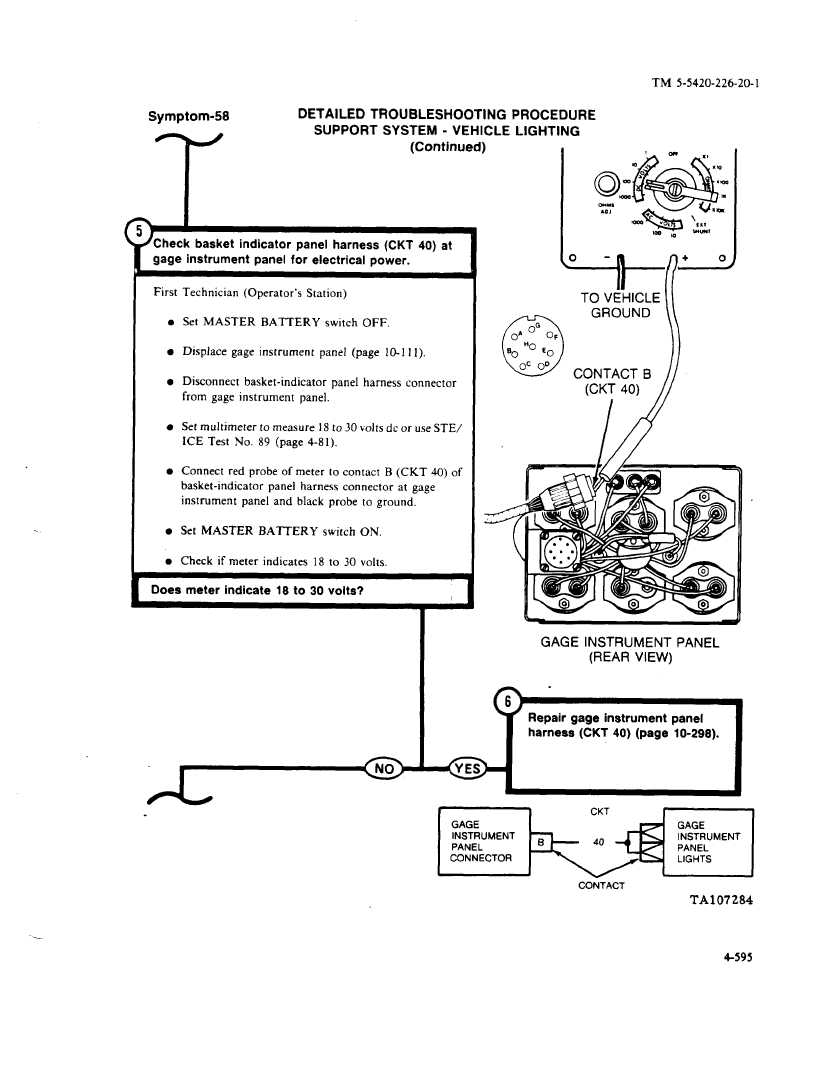
Check
basket
indicator
panel harness
(CKT 40) at
gage instrument
panel for electrical
power.
First
l
l
l
l
l
l
l
Technician
(Operator’s
Station)
Set MASTER
BATTERY
switch
OFF.
Displace
gage instrument
panel
(page
10-111).
Disconnect
basket-indicator
panel
harness
connector
from gage instrument
panel.
Set multimeter
to measure
18 to 30 volts dc or use STE/
ICE Test
No,
89 (page 4-81).
Connect
red probe of meter
to contact
B (CKT
40) of
basket-indicator
panel
harness
connector
at gage
instrument
panel
and black
probe
to ground.
Set MASTER
BATTERY
switch
ON.
Check
if meter
indicates
18 to 30 volts.
Q’i’g&”
mm
AO,
%
v.:
+
\
!mn
v ,
,x,
‘-
10 **’
Y’
TO VEHICLE
GROUND
[
L)
o~“o~
no
E’o
‘o
Oc OD)CONTACTB(CKT 40)/
Does meter
indicate
18 to 30 volts?
I
(
I
h
GAGE INSTRUMENT
PANEL
(REAR VIEW)
.
)
Repair gage instrument
panel
harness
(CKT 40) (page
10-298).
CONTACT
TA107284
4-595